


 MODEL TELEMETRY screen explanation / How to use telemetry
This section describes how to use TELEMETRY screen of OpenTX / EdgeTX radio.
このページを日本語で見る
Table of contents
MODEL TELEMETRY screen functions
TELEMETRY screen in MODEL menu is used to read various telemetry data (sensor measurement values such as current battery voltage/current, motor rotation speed, temperature, e.t.c) sent from the receiver (aircraft). You can decide which telemetry data to read or record in the log, and register it in the MODEL information. You can also use the read telemetry data to calculate on the radio and register it as a new telemetry value.Telemetry data registered on TELEMETRY screen can be displayed on the custom telemetry screen during operation using DISPLAY screen . And you can also save them in a log file using Special Functions/Global Functions .
MODEL TELEMETRY screen explanation
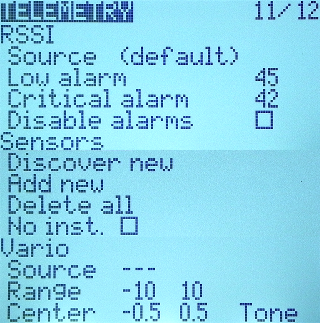 If you open "TELEMETRY" screen from "MODEL menu", the screen will look like this.
This screen is roughly divided into three columns: "RSSI" column, "Sensors" column, and "Vario" column.
If you open "TELEMETRY" screen from "MODEL menu", the screen will look like this.
This screen is roughly divided into three columns: "RSSI" column, "Sensors" column, and "Vario" column.
In "RSSI" column, you can set alarms for RSSI (Receiver Signal Strength Indicator).
In "Sensors" column, you can detect and set telemetry sensors installed in the aircraft.
In "Vario" column, you can set the Variometer that detects ascent and descent of aircraft. Variometer is commonly used in radio-controlled gliders.
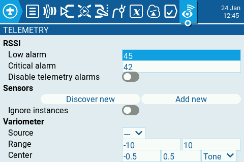 You can set color display / touch panel model in the same way.
RSSI alarm setting
RSSI value is 100(db) when the reception is the best, for example when the transmitter and receiver are close enough. And it drops by 6(db) for every doubling of the distance between the transmitter and receiver. Usually when RSSI is below about 38(db) the aircraft will be out of control.For OpenTX/EdgeTX, it is recommended to set [Low alarm] to 45(db) and [Critical alarm] to 42(db). Therefore, for example, if [Critical alarm] is heard when the distance between the transmitter and receiver is 1000m, it is considered that control will be lost when the distance is about 1500m.
However, the distance between the transmitter and receiver cannot be determined from the RSSI value. Please use it as a reference value.
You can read more about RSSI signal on Telemetry Values page of OpenTX official site.
Telemetry Values (OpenTX)
The meaning of each setting item in the RSSI column is as follows.
| item | description |
|---|---|
| Source | Specifies the sensor to use as RSSI. It is normally fixed to "default" and cannot be changed. |
| Low alarm | "RF signal low" warning sounds when the RSSI value falls below the value specified here. Normally set 45 (db) here. |
| Critical alarm | "RF signal critical" warning sounds when the RSSI value falls below the value specified here. Normally set 42 (db) here. |
| Disable alarms | If you check here, RSSI warning will not be notified. In this case, a warning screen "RSSI WARNING" will be displayed when the radio is started. |
Variometer alarm setting
Variometer detects changes in aircraft altitude as rate of climb/descent (in meters/second or feet/second). In OpenTX/EdgeTX, this change in rising/falling rate is notified as a change in alarm pitch. Use the Variometer menu on RADIO SETUP screen to set the actual frequency to be played.
RADIO SETUP setting items explanation
The meaning of each setting item in the Vario column is as follows.
| item | description |
|---|---|
| Source | Specifies the sensor to use as a variometer. Select from the telemetry sensors registered in Sensors field. |
| Range | Specify the range over which the pitch of the Variometer alarm is varied. If climb/descent rate is within the range specified here, alarm pitch will change according to that value. When it goes beyond the range specified here, alarm pitch will stop changing. Units are meters/second or feet/second. |
| Center | Specify the range for ignoring changes in climb/descent rates. When the climb/descent rate is within the range specified here, the alarm pitch will not change. This is set to absorb fluctuations in the median value of the Variometer. Therefore, the range specified by [Center] is usually within the range specified by [Range]. Units are meters/second or feet/second. |
| Tone/Silent | Specifies whether to sound an alarm when climb/descent rate is within the range specified by [Center]. |
Telemetry data setting
In the Sensors column, you can set telemetry datas obtained from aircraft.The meaning of each setting item in the Sensors column is as follows.
| item | description |
|---|---|
| Discover New | Move cursor here and press [ENTER] key to automatically detect telemetry datas sent from the bound receiver (aircraft) and register them in MODEL information. This menu must be operated while the receiver is powered on and bound to the radio. |
| Add New | Move cursor here and press [ENTER] key to open telemetry sensor registration screen. You can manually register telemetry sensors. |
| Delete All | Move cursor here and press [ENTER] key to delete all detected and registered telemetry sensors from MODEL information. |
| No inst. (No Instances) / Ignore instances |
Checking this will solve the problem that same telemetry data is notified as output (instance) of multiple different sensors.
This issue is a software bug in the sensor and this feature is not normally required.
In OpenTX/EdgeTX Companion "Telemetry" screen, this item is labeled "disable multi sensor handling". |
Auto detect telemetry sensors
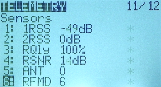 Move cursor to [Discover New] in "Sensors" column and press [ENTER] key while the receiver (aircraft) and radio are bound.
Then, as shown in this figure, telemetry sensor information are read from the receiver.
Move cursor to [Discover New] in "Sensors" column and press [ENTER] key while the receiver (aircraft) and radio are bound.
Then, as shown in this figure, telemetry sensor information are read from the receiver.
When the value of each sensor is updated, "*" mark blinks to the right of the sensor value. Sensors that are frequently updated will have an "*" mark not blink, left on.
Once sensor names are read, these are saved in MODEL information. Values of these sensors can be displayed on the custom telemetry screen during flight using DISPLAY screen .
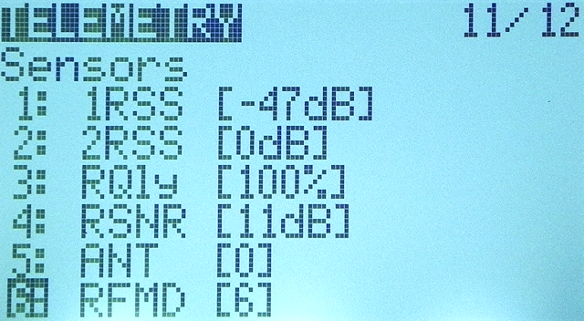 If communication with the receiver is lost, or if for some reason the telemetry sensor information is not updated, the value will be enclosed in "[]" (square brackets).
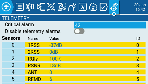 You can set color display / touch panel model in the same way.
When the value of each sensor is updated, the "●" mark blinks to the right of the sensor name.
Sensors that are frequently updated will have the "●" mark not blink, left on.
You can set color display / touch panel model in the same way.
When the value of each sensor is updated, the "●" mark blinks to the right of the sensor name.
Sensors that are frequently updated will have the "●" mark not blink, left on.
Once sensor names are read, these are saved in MODEL information. Values of these sensors can be displayed on the main screen during flight using widgets .
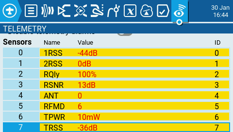 If communication with the receiver is lost, or if for some reason the telemetry sensor information is not updated, the value text turns red.
Manually register telemetry sensors
 Move cursor [Add New] in "Sensors" column and press [ENTER] key.
Then you will see a screen like this.
By entering each item on this screen, you can manually register the telemetry sensor.
When registering sensor manually, there is no need to bind receiver and radio.
Move cursor [Add New] in "Sensors" column and press [ENTER] key.
Then you will see a screen like this.
By entering each item on this screen, you can manually register the telemetry sensor.
When registering sensor manually, there is no need to bind receiver and radio.
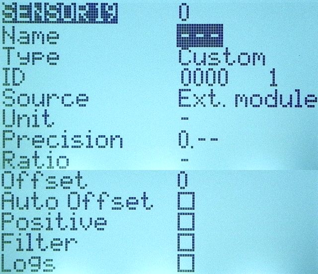
There are two types of sensors that can be registered: [Custom] and [Calculated]. See the "Type" column in the table below for these differences.
This is the screen when [Custom] is selected in [Type] field.
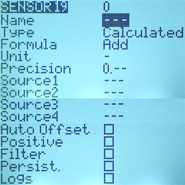 If you select [Calculated] in [Type] field, the screen will look like this.
The meaning of each field is as shown in the table below.
If you select [Calculated] in [Type] field, the screen will look like this.
The meaning of each field is as shown in the table below.
| item | description |
|---|---|
| Name | Specifies the name of the sensor. Enter up to 4 alphanumeric characters, spaces, and hyphens. |
| Type |
Specifies the sensor type.
[Custom] or [Calculated] can be specified.
Selecting [Custom] allows you to manually define hardware sensors that are not automatically registered by [Discover New] function. Selecting [Calculated] allows you to define a sensor whose value is calculated using other sensors values. For example, you can set a sensor to display power by multiplying the values of a voltage sensor and a current sensor. |
| ID |
This is ID number that indicates what kind of sensor it is, and specifies a value determined for each sensor.
It consists of two values.
The first is a 4-digit number that specifies ID number and the second is a 1-digit number that specifies the instance number. ID number is defined for each sensor type. Instance number is defined for each sensor hardware. If multiple sensors of the same type (ID number) are connected, the instance number must be different for each piece of hardware to distinguish between them. To change the instance number, you need to connect a device called "Sensor ID Changer" to the sensor. |
| Source | Displays the transmitter used (Int. (built-in)/Ext. (external)). This cannot be changed by the user. |
| Unit | Specify units. This unit is appended when the sensor value is displayed on the screen or read aloud. |
| Precision |
Specifies the number of digits after the decimal point when the sensor value is displayed on the screen.
[0.–-]: Truncate after the decimal point. [0.0]: Display one decimal place. Truncate after 2 digits. [0.00]: Display two decimal places. Truncate after 3 digits. |
| Ratio | Specifies the "ratio" value to multiply with the sensor value. Some sensors require a certain "ratio" value to be accumulated to read the correct value. |
| Offset | Specifies the "offset" value to add to the sensor value. The "offset" value specified here will be added to the sensor values displayed on the screen. |
| Auto Offset | If you check here, the initial value of the sensor will be subtracted from the sensor value. For example, if you set this for an altitude sensor that reads sea level, you can see the relative altitude from the takeoff point. |
| Positive | If you check here, the value of the sensor will be displayed only when it is a positive number. Displays zero when the sensor value becomes a negative number. |
| Filter | If you check here, the sensor values will be smoothed. Displays the average of recent sensor values. |
| Logs | If you check here, the value of this sensor will be saved in the log file. Log collection settings are made in "SD Logs" action in Special Functions/Global Functions . |
| Formula | Specify the calculation formula for [Calculated] type sensor. See Formula for Calculated sensor for more information |
| Source1, 2, 3, 4 | Specifies the arguments to be used for the calculation of [Calculated] type sensor. |
| Persist. (Persistent) | If you check here, the sensor values will be saved when switching models or powering down the radio, and the saved values will be restored when flying with that model again. |
Formulas for Calculated type sensor
For Calculated type sensors, the following formulas can be specified. Arguments are specified in "Source1, 2, 3, 4" fields. Arguments are selected from the telemetry sensors registered in Sensors column and their sign-inverted values. However, depending on the formula you choose, you may need to specify formula-specific arguments.| formula | description |
|---|---|
| Add | Add the values of multiple sensors. You can enter up to 4 values. |
| Average | Calculates the average value of multiple sensor values. You can enter up to 4 values. |
| Minimum | Find the minimum value of multiple sensor values. You can enter up to 4 values. |
| Maximum | Find the maximum value of multiple sensor values. You can enter up to 4 values. |
| Multiply | Multiply the values of the two sensors. |
| Totalize | Cumulatively add the values of one sensor. |
| Cell |
This is the formula for FrSKY Lipo battery sensor.
Displays cell voltage specified by the number in "Cell index" field. If you specify "Lowest" in "Cell index" field, the voltage of the cell with the lowest is displayed. If you specify "Highest" in "Cell index" field, the voltage of the cell with the highest is displayed. If you specify "Delta" in "Cell index" field, the voltage difference between lowest and highest cell is displayed. |
| Consumpt (Consumption) | Calculate the power consumption (mAh) by cumulatively add the values of current sensor. |
| Distance | Calculates the distance between the receiver (aircraft) and the radio (pilot) using GPS sensor and altimeter values. |
Edit or delete telemetry data
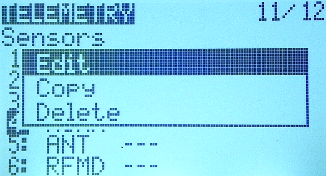 Move cursor to the name of telemetry data registered in Sensors column of TELEMETRY screen,
then press and hold [ENTER] key to display a menu like this.
Move cursor to the name of telemetry data registered in Sensors column of TELEMETRY screen,
then press and hold [ENTER] key to display a menu like this.
Select [Edit] to edit the telemetry data settings.
Select [Copy] to copy the telemetry data settings.
Select [Delete] to delete the telemetry data setting.
Reset telemetry data
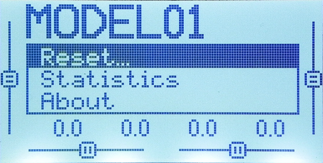 You can reset telemetry datas from the menu that appears when you press and hold [ENTER] key on the main screen.
On monochrome screen models, selecting [Reset] menu here displays a further submenu. Select [Reset telemetry] from the submenu to reset all telemetry at once. Select [Flight] from the submenu resets all timers and telemetry at once.
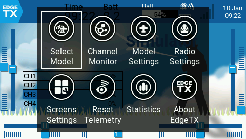 For color display / touch panel models, tap the top bar (touch panel models) or click [ENTER] key on the main screen to display such a menu (main navigation menu).
Select [Reset Telemetry] from the menu to display a further submenu.
For color display / touch panel models, tap the top bar (touch panel models) or click [ENTER] key on the main screen to display such a menu (main navigation menu).
Select [Reset Telemetry] from the menu to display a further submenu.
Select [Reset telemetry] from the submenu to reset all telemetry at once. Select [Reset Flight] to reset the timer and telemetry at once.
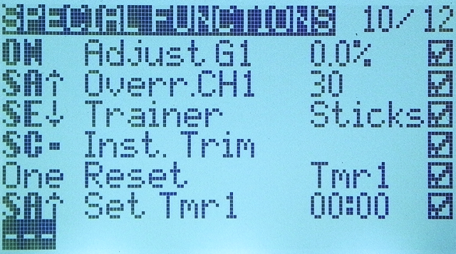 Alternatively, you can use "Reset" action in
Special Functions/Global Functions
to reset telemetry datas.
You can reset them with operations such as switches.
Alternatively, you can use "Reset" action in
Special Functions/Global Functions
to reset telemetry datas.
You can reset them with operations such as switches.
How to use Special Functions / Global Functions
To know more about How to Fly Hobby Drone
To know more about iPhone