


 Create a new MODEL / setting on PC

The same operation is possible with any radio that uses OpenTX / EdgeTX. However, keyswitch assignments / functions differ depending on model, and screen / menu configuration differs depending on installed version of OpenTX / EdgeTX.
このページを日本語で見る
Table of contents
-
RadioMaster Zorro 2.4GHz 16CH Hall Sensor Gimbals

RadioMaster 2022/02 USD89.99
On-board firmware:EdgeTX(OpenTX)
Featuring an ergonomic design, large bright LCD screen in the perfect viewing position, travel adjustable HALL sensor gimbals, a nano size external RF module bay

 (US)
(UK)
How to use RadioMaster Zorro
(US)
(UK)
How to use RadioMaster Zorro
Register a new MODEL input area
You can create models using OpenTX/EdgeTX Companion installed on your PC. First, read model information from radio, then create and edit them on OpenTX/EdgeTX Companion, and write it back to the radio. The model information for up to 60 aircrafts stored in the radio is managed as one ".otx" format binary file on PC. You can manage by creating multiple ".otx" format files on your computer and transferring them to the radio as needed. This way, an infinite number of model information can be used in one radio.
How to install OpenTX Companion
How to install EdgeTX Companion
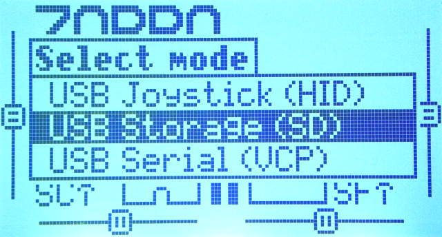 When you turn on the radio and connect it to your PC with USB cable, a menu like this will be displayed.
Select "USB Storage(SD)" to create and edit models.
Then, after waiting for a while (about 20-30 seconds), two drives, "ESD-USB" or "USB drive", and "Taranis" or "(your radio name)" will be mounted in Explorer on your computer.
When you turn on the radio and connect it to your PC with USB cable, a menu like this will be displayed.
Select "USB Storage(SD)" to create and edit models.
Then, after waiting for a while (about 20-30 seconds), two drives, "ESD-USB" or "USB drive", and "Taranis" or "(your radio name)" will be mounted in Explorer on your computer.
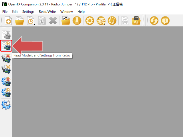 Start OpenTX/EdgeTX Companion.
Then, click second icon from the top, "Read Models and Settings From Radio" on the left side of the screen.
Then, model information etc. saved in the radio will be loaded into OpenTX/EdgeTX Companion.
Start OpenTX/EdgeTX Companion.
Then, click second icon from the top, "Read Models and Settings From Radio" on the left side of the screen.
Then, model information etc. saved in the radio will be loaded into OpenTX/EdgeTX Companion.
If you select [File]-[New] from the menu here, you can create a completely new ".otx" format file. If you select [File]-[Open], you can read ".otx" format file stored in your computer.
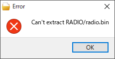 When loading settings from the radio, you may see the error "Can't extract RADIO/radio.bin" as shown in the figure.
If your radio is a recently released product and OpenTX/EdgeTX Companion does not yet support it, you may see an error like this.
In that case, please wait for the version upgrade of OpenTX/EdgeTX Companion.
When loading settings from the radio, you may see the error "Can't extract RADIO/radio.bin" as shown in the figure.
If your radio is a recently released product and OpenTX/EdgeTX Companion does not yet support it, you may see an error like this.
In that case, please wait for the version upgrade of OpenTX/EdgeTX Companion.
EdgeTX, which has a faster development pace than OpenTX, may already support even radios that OpenTX does not support. If you are using OpenTX, you may consider migrating to EdgeTX.
If you see this error even though your radio is supported by OpenTX/EdgeTX Companion, the model information file stored in the radio may be corrupted. It may be solved by initializing or replacing microSD card or updating the firmware of the radio.
List of radios currently supported by OpenTX Companion (OpenTX)
How to install EdgeTX on the radio
How to install EdgeTX Companion
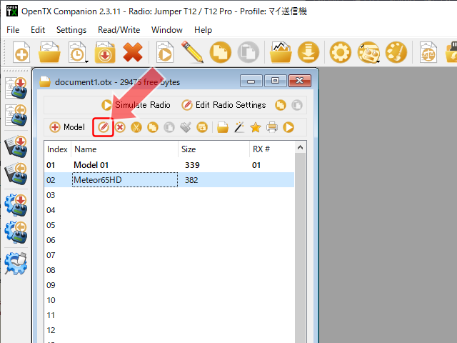
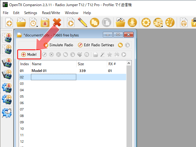 Then model list is displayed like this.
You can register aircraft informations of 60 aircraft as a "MODEL" here.
At first, dummy aircraft information called "Model 01" is registered in the first area.
In the example shown in the figure, the dummy aircraft information "Model 01" is registered in the first area.
Currently selected model name is displayed in bold.
Then model list is displayed like this.
You can register aircraft informations of 60 aircraft as a "MODEL" here.
At first, dummy aircraft information called "Model 01" is registered in the first area.
In the example shown in the figure, the dummy aircraft information "Model 01" is registered in the first area.
Currently selected model name is displayed in bold.
You can edit this "Model 01", but let's newly register it in the second area here. Click "02" column and click
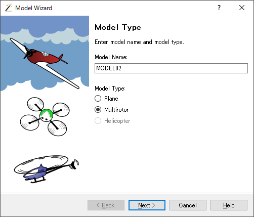 Then the "Model Wizard" screen will open.
This allows you to first assign stick channels (Mixes screen setting) and then set some timers.
Then the "Model Wizard" screen will open.
This allows you to first assign stick channels (Mixes screen setting) and then set some timers.
Click Cancel if you do not want to use this wizard.
When using the wizard, enter a name of your choice in "Model name", and for Tiny Whoop, select "Multirotor" and click "Next".
 If you want to use the wizard, then assign stick channels.
If you want to change channels, select it from the drop-down list.
Click Next when done.
If you want to use the wizard, then assign stick channels.
If you want to change channels, select it from the drop-down list.
Click Next when done.
| Behavior name | Name of control |
|---|---|
| Throttle | - |
| Roll | Aileron |
| Pitch | Elevator |
| Yaw | Rudder |
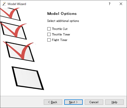 Then you will see a screen like this. Select whether to set three options automatically.
Check the items you want to set and click "Next".
Then you will see a screen like this. Select whether to set three options automatically.
Check the items you want to set and click "Next".
Throttle Cut
The function that cuts throttle is automatically set in the throttle channel of Mixes screen. A setting is added so that throttle will have a weight of -100 when switch up.
Throttle Timer
Sets a timer that counts the amount of time throttle has been in operation (non-zero position). A timer is automatically set so that trigger is THs and initial counter value is 00:00:00.
Flight Timer
Set a timer that counts the total time since throttle first reached a non-zero position. A timer is automatically set so that trigger is THt and initial counter value is 00:00:00.
How to use timer
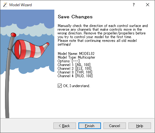 The end of the wizard screen looks like this.
Check "OK, I understand" and click "Finish" to save.
The end of the wizard screen looks like this.
Check "OK, I understand" and click "Finish" to save.
 In the second entry, we have a new model.
You can start editing this model by clicking
In the second entry, we have a new model.
You can start editing this model by clicking
You can use icons to the right of this icon to perform operations such as "delete", "cut", "copy", "paste", and "insert" the model. You can also copy an already created model and edit a part of it.
On PC: Setup screen settings
 Select a model on model list screen and click
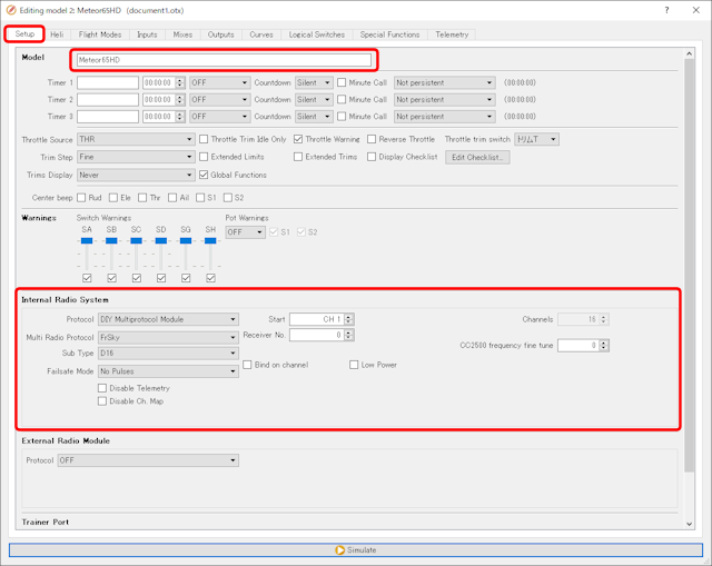
First, click "Setup" tab. This is the screen for basic model settings. All you need to enter on this screen is the model name and transmission protocol settings. Enter any model name in "Model" field. You can use alphanumericals, white spaces, and hyphens in the model name.
For details on these all setting items, see MODEL SETUP setting items explanation .
 Next, set transmission protocol.
When using a transmitter built into the radio, set "Internal Radio System" field,
When using a transmitter installed in module bay, set it in "External Radio Module" field.
Here, set communication protocol of drone that you checked in advance.
Next, set transmission protocol.
When using a transmitter built into the radio, set "Internal Radio System" field,
When using a transmitter installed in module bay, set it in "External Radio Module" field.
Here, set communication protocol of drone that you checked in advance.
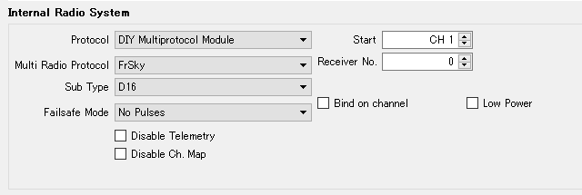
Drone to be bound this time uses "D16" type in Frsky protocol. Select "DIY Multiprotocol Module" in "Multi Radio Protocol" field. Select "FrSky" in "Multi Radio Protocol" field and "D16" in "Sub Type" field. No other changes are required.
This setting screen changes depending on the protocol selected. Depending on the protocol, it may be necessary to set other items as well. Check website or instruction manual of FC board or receiver board.
For information on how to set the communication protocol when using the ExpressLRS (ELRS) protocol, see How to set up ExpressLRS transmitter .
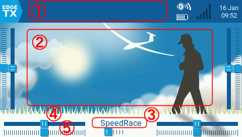 Depending on the type of radio, you can set Main screen and Model Image.
Model Image is displayed as an image of the selected aircraft on main screen and
MODELSEL screen
.
See below for details.
Depending on the type of radio, you can set Main screen and Model Image.
Model Image is displayed as an image of the selected aircraft on main screen and
MODELSEL screen
.
See below for details.
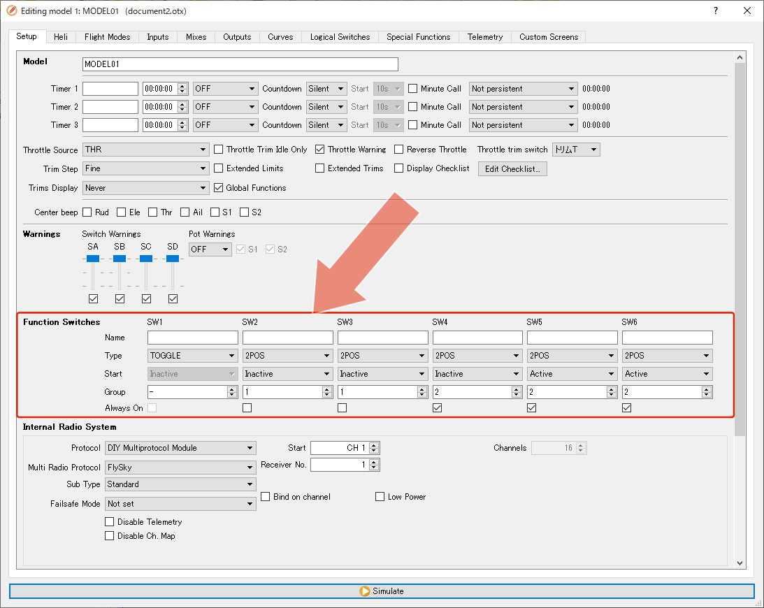 On the front panel of recent radios that support OpenTX / EdgeTX, there are products with 6 buttons.
These switches are called "function switches".
Different behavior can be set for each "MODEL" set in the radio.
See below for details.
On the front panel of recent radios that support OpenTX / EdgeTX, there are products with 6 buttons.
These switches are called "function switches".
Different behavior can be set for each "MODEL" set in the radio.
See below for details.
Depending on communication protocol selected, "Failsafe mode" field on this screen allows you to specify how the drone behaves when communication between radio and drone is lost. See Failsafe settings for details.
Failsafe settings
On PC: Input screen settings
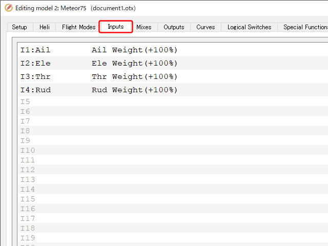 This screen lists input devices used for maneuvering. It can also be thought of as a screen that assigns input devices such as sticks, switches, and LOGICAL SWITCHES mounted on the radio to virtual channels defined inside OpenTX/EdgeTX.
Number / name of the virtual channel is lined up after the [I] mark on the far left.
This screen lists input devices used for maneuvering. It can also be thought of as a screen that assigns input devices such as sticks, switches, and LOGICAL SWITCHES mounted on the radio to virtual channels defined inside OpenTX/EdgeTX.
Number / name of the virtual channel is lined up after the [I] mark on the far left.
First four channels are already assigned Aileron, Elevator, Throttle, Rudder in that order. This allocation order is determined by specifying "Default Channel Order" field on [Settings]-[Settings] menu screen. Since it is a virtual channel, it can be assigned in any order. If this order does not match the aircraft you are binding to, change it on next Mixes screen.
 Assign switches to virtual channels 5-8.
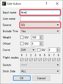
If you double-click "I5" column on the screen above, you will see a screen like this.
There are many settings that can be made regarding the behavior of input device, but this time we will only assign the switch.
Assign switches to virtual channels 5-8.
If you double-click "I5" column on the screen above, you will see a screen like this.
There are many settings that can be made regarding the behavior of input device, but this time we will only assign the switch.
In the "Source" field, select SG (Switch G) that will be the input device. You can give this virtual channel a name in "Input name" field. Since Arm is assigned to SG this time, I named it "Arm". You can leave the name blank.
Similarly, assign SA, SD, SH to virtual channels 6-8. Since it is a virtual channel, it can be assigned in any order.
For details on these all setting items, see MODEL INPUTS setting items explanation .
If you simply assign one switch to one channel, you can register it directly in "Source" field of next Mixes screen without registering the switch on this Input screen.
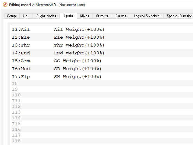 When screen looks like this, setting of Input screen is complete.
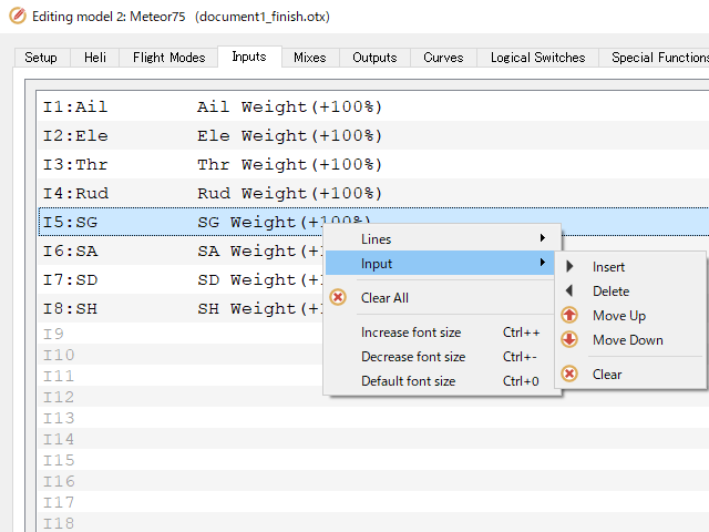 If you right-click on a channel already been entered, a screen like this will be displayed.
You can edit, insert new inputs before and after, move and delete.
If you right-click on a channel already been entered, a screen like this will be displayed.
You can edit, insert new inputs before and after, move and delete.
On PC: Mixes screen settings
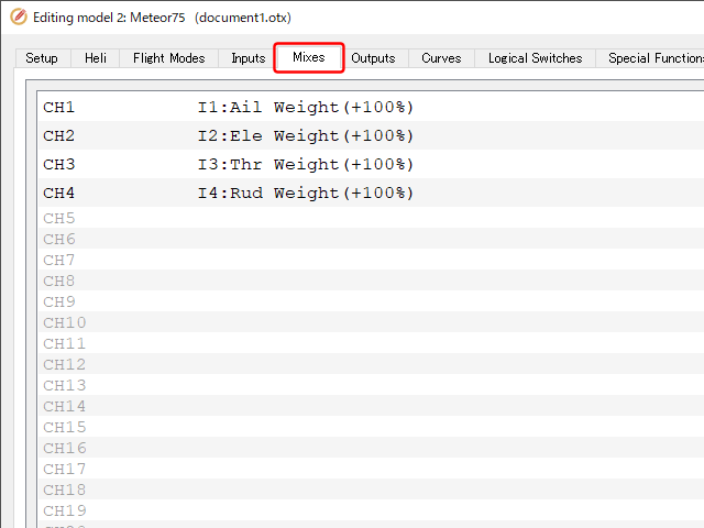 This screen defines which input device (virtual channel) defined on Input screen is transmitted to which physical channel of receiver (aircraft).
Destination channel number is lined up on the far left, and the number of assigned virtual channel is lined up next to it.
This screen defines which input device (virtual channel) defined on Input screen is transmitted to which physical channel of receiver (aircraft).
Destination channel number is lined up on the far left, and the number of assigned virtual channel is lined up next to it.
First four channels are already assigned Aileron, Elevator, Throttle, Rudder in that order.
 Allocate virtual channels to physical channels 5-8.
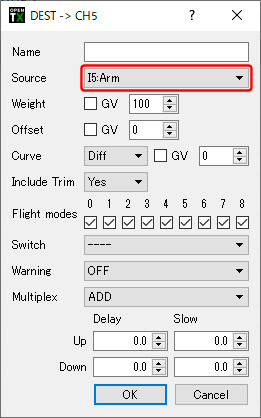
If you double-click CH5 column on the screen above, you will see a screen like this.
There are many settings that can be made regarding the behavior of virtual channels, but this time we will only assign channel numbers.
Allocate virtual channels to physical channels 5-8.
If you double-click CH5 column on the screen above, you will see a screen like this.
There are many settings that can be made regarding the behavior of virtual channels, but this time we will only assign channel numbers.
In "Source" field, select virtual channel [I5]. This time, "I5" is named "Arm", so select [I5:Arm].
When we defined virtual channels, we specified the same number as the physical channel, so simply set [I5:Arm] for CH5, [I6:Mod] for CH6, [I7:Flp] for CH7.
For details on these all setting items, see MODEL MIXES setting items explanation .
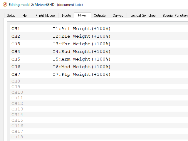 When Mixes screen looks like this, setting is complete.
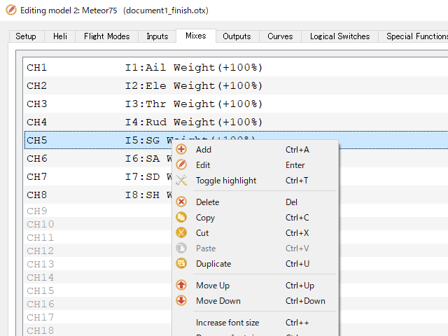 If you right-click on a channel already been entered, a screen like this will be displayed.
You can add, edit, delete, copy, cut, duplicate, and change the order.
If you right-click on a channel already been entered, a screen like this will be displayed.
You can add, edit, delete, copy, cut, duplicate, and change the order.
On PC: Write back model information to radio
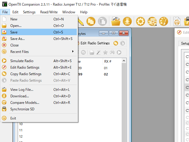 After creating and editing model, first save the model information on your computer for back-up.
Simply select [File]-[Save] or [File]-[Save As] from the menu.
After creating and editing model, first save the model information on your computer for back-up.
Simply select [File]-[Save] or [File]-[Save As] from the menu.
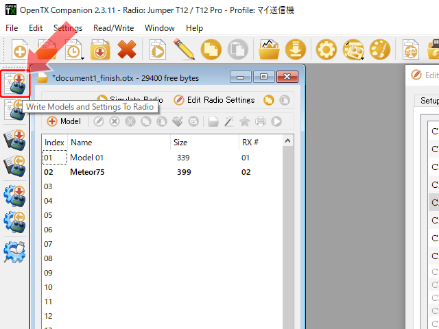 Next, let's transfer the model information to radio.
Click "Write Models and Settings To Radio" at top of icons on the left side of the screen.
Next, let's transfer the model information to radio.
Click "Write Models and Settings To Radio" at top of icons on the left side of the screen.
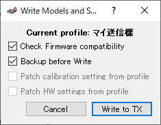 Then you will see a screen like this.
Set "Check Firmware compatibility" and "Backup before write" as you like.
Then you will see a screen like this.
Set "Check Firmware compatibility" and "Backup before write" as you like.
If you click "Write to TX" here, the model information will be written to radio.
Create MODEL, Bind with drone, Test flight
Precautions when removing radio from computer
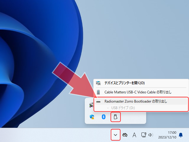 When radio is connected to PC in "USB Storage (SD)" mode, memory of the radio is visible as a USB memory.
When removing radio from PC, perform "Eject" operation of two drives, "ESD-USB" or "USB drive", and "Taranis" or "(your radio name)", and then remove it, in the same way as when removing USB memory.
When radio is connected to PC in "USB Storage (SD)" mode, memory of the radio is visible as a USB memory.
When removing radio from PC, perform "Eject" operation of two drives, "ESD-USB" or "USB drive", and "Taranis" or "(your radio name)", and then remove it, in the same way as when removing USB memory.
To know more about How to Fly Hobby Drone
To know more about iPhone