


 MODEL OUTPUTS setting items explanation
This section describes the setting items on the MODEL OUTPUTS screen of OpenTX / EdgeTX radio.
このページを日本語で見る
Table of contents
MODEL OUTPUTS screen functions
This screen is used to adjust maximum, minimum, and trim of the pulse length for each physical channel defined on MIXES screen . Adjust logical control signal to fit the range of actual servo motion. You can also reverse the direction of servo rotation.MODEL OUTPUTS screen explanation
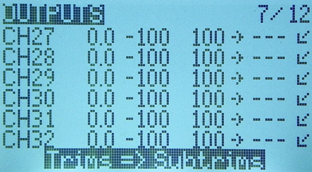
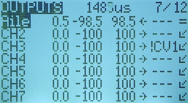 If you open "OUTPUTS" screen from "MODEL menu", the screen will look like this.
32 channels output settings of CH1 to CH32 are listed.
The number to the right of the word "OUTPUTS" at the top of screen is actual output pulse length (μsec) of currently selected channel (at cursor position).
Operate stick or switch assigned to this channel to change this value.
If you open "OUTPUTS" screen from "MODEL menu", the screen will look like this.
32 channels output settings of CH1 to CH32 are listed.
The number to the right of the word "OUTPUTS" at the top of screen is actual output pulse length (μsec) of currently selected channel (at cursor position).
Operate stick or switch assigned to this channel to change this value.
The meaning of each field is Name, Subtrim, Min, Max, Direction, Curve, Subtrim mode from left to right. Any item can be entered on detailed setting screen (described later).
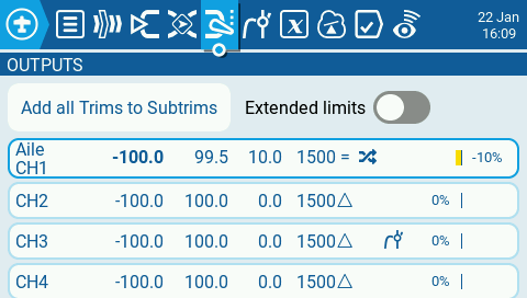 You can set color display / touch panel model in the same way.
The meaning of each field is Name, Min, Max, Subtrim, PPM Center, Subtrim mode, Inverted, Curve, Actual output (%) from left to right. Any item can be entered on detailed setting screen (described later).
| field | item | description |
|---|---|---|
| 1 | Name | Number of this channel. If you name this channel, its name will be displayed instead of the channel number. |
| 2 | Subtrim | Sub-trim value set for this channel. |
| 3 | Min | The lower limit of servo movement for PPM Center value (described later). Normally, it is displayed in the range of -100.0% to 0.0%. However, if you have enabled build option "ppmus" when updating radio firmware , it will be displayed in the range of -512.0 μsec to 0.0 μsec. |
| 4 | Max | The upper limit of servo movement for PPM Center value. Normally, it is displayed in the range of 0.0% to +100.0%. However, if you have enabled build option "ppmus" when updating radio firmware , it will be displayed in the range of 0.0 μsec to +512.0 μsec. |
| 5 | Direction / Inverted |
Shows direction of increase / decrease of output value when stick or switch is operated.
"→" or blank is displayed for normal direction, and "←" or
|
| 6 | Curve |
Curve number assigned to this channel.
On color display / touch panel models,
MODEL CURVES screen explanation / How to use curves
|
| 7 | Subtrim mode | Displays whether to shift maximum and minimum values according to sub-trim setting. When "△" is displayed, it means not to shift, and when "=" is displayed, it means to shift. |
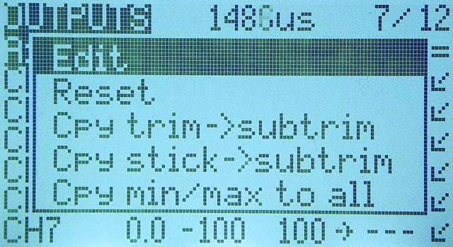 Select any channel number or channel name and press [ENTER] to display the menu shown in this figure.
The meaning of each menu is as follows.
Select any channel number or channel name and press [ENTER] to display the menu shown in this figure.
The meaning of each menu is as follows.
- Edit
- Open detailed setting screen for selected channel.
- Reset
- Initializes advanced settings for selected channel. This is convenient when you want to start setting from the beginning.
- Cpy trim->subtrim (Copy trims to subtrim)
-
Copy current
trim switch
settings for selected channel to sub-trim field of corresponding OUTPUTS screen.
After copying, trim switch setting should be set to zero (center).
Otherwise the trim will be twice as effective.
Note that nothing happens when you select a channel for which trim switch is not set. - Cpy stick->subtrim (Copy sticks to subtrim)
-
Copy current stick input of selected channel to sub-trim field of corresponding OUTPUTS screen.
Note that nothing happens when you select a channel for which trim switch is not set. - Cpy min/max to all (Copy min/max to all)
- Copy the settings in Min / Max field of selected channel to all other channels.
 At the bottom of "OUTPUTS" screen, there is a line that says "Trims => Subtrims".
If you press [ENTER] here, you can copy current settings of four trim switches to sub-trim column of corresponding four channels at once.
At the bottom of "OUTPUTS" screen, there is a line that says "Trims => Subtrims".
If you press [ENTER] here, you can copy current settings of four trim switches to sub-trim column of corresponding four channels at once.
For details on trim switch, see How to use trim switches page.
How to use trim switches
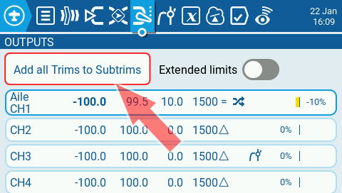 On color display / touch panel models, this function is located at the top of "OUTPUTS" screen.
Also, if you turn on "Extended Limits" on the right, servo movable range will be extended to 150% (1500±768μsec) (standard is 100% (1500±512μsec)). On monochrome display models, this setting is on MODEL SETUP screen .
MODEL OUTPUTS setting items explanation

Channel number is displayed to the right of the word "OUTPUTS" at the top of the screen. To the right is actual output pulse length (μsec) for this channel. If you change parameters below or operate stick or switch assigned to this channel, the value here will change.

| item | description |
|---|---|
| Name | You can name this channel. Enter up to 4 alphanumers, spaces, and hyphens. |
| Subtrim |
Specifies a sub-trim for adjusting center position of this channel.
Specify in the range of -100.0% to + 100.0%. You can also select a
global variable
by pressing and holding ENTER while editing.
How to use trim switches
|
| Min | Specifies lower limit of servo movement for PPM Center value. Output pulse of the channel never falls below this lower limit. Normally, specify in the range of -100.0% to 0.0%. If the build option "ppmus" is enabled when updating firmware of the radio, it can be specified in the range of -512.0 μsec to 0.0 μsec. You can also select a global variable by pressing and holding ENTER while editing. |
| Max | Specifies upper limit of servo movement for PPM Center value. Output pulse of the channel never exceeds this upper limit. Normally, specify in the range of 0.0% to +100.0%. If the build option "ppmus" is enabled when updating firmware of the radio, it can be specified in the range of 0.0 μsec to +512.0 μsec. You can also select a global variable by pressing and holding ENTER while editing. |
| Direction / Inverted |
Specifies direction of increase / decrease in output value when stick or switch is operated.
Select "---" for normal direction. Select "INV" to reverse the direction (servo inversion).
On color display / touch panel models, turning it on will reverse the direction (servo inversion). |
| Curve |
Specifies reaction curve that determines output value for input value from MIXES screen (mixer).
Specify the number of custom curve created on CURVES screen of MODEL menu.
Input value will be converted according to the curve specified here.
Select from "---" (invalid), CV1 ~ CV32, and! CV1 ~! CV32 (inverted).
MODEL CURVES screen explanation / How to use curves
|
| PPM Center |
Specify pulse length as median value of this channel in μsec.
Specify in the range of 1000 to 2000.
Changing this will shift the entire servo range, including upper and lower limits.
Also, the situation cannot be confirmed on the main screen "CHANNELS (MIXERS) MONITOR".
The default values are a median of 1500 μsec, a minimum of PPM Center value - 512μsec (when Min value is -100%), and a maximum of PPM Center value + 512μsec (when Max value is +100%). |
| Subtrim mode |
Specify whether to shift maximum and minimum values according to sub trim setting.
If you select "△" (Asymmetrical), only the center value shifts and the upper and lower limits do not change. Therefore, the reaction of the stick (curve slope) differs between the upper half and the lower half from center value. If you select "=" (Symmetrical), the upper and lower limits will shift according to the shift of the center value. The reaction of the stick is the same on both sides of the median. However, there will be a section where the stick does not respond (clipped) near the upper or lower limit. For example, if Min is set to -100%, Max is set to + 100%, and sub trim is set to +20, if you select "△", the minimum value remains -100% and the maximum value remains + 100%. When you move the stick, the output value changes smoothly from the minimum value to the maximum value. However, the reaction of the stick is different between the upper half and the lower half from the center value. On the other hand, if you select "=", the minimum value will be -80% and the maximum value will be +100% (the part that exceeds the upper limit will be clipped to +100%). In the section near the maximum value, output value remains +100% even if stick is moved. You can read the explanation of the behavior of this parameter with figures on Outputs explanation page of the OpenTX official site. |
To know more about How to Fly Hobby Drone
To know more about iPhone