

 How to use Google Earth Decoder to create MSFS scenery on Google Maps

YouTube is a waste of time, so here we will summarize the key points of how to use the free tool: Google Earth Decoder.
このページを日本語で見る
Contents
- Compatibility with MSFS2024
- Check out the 3D map on Google Earth
- Installation of various development tools
- Naming the package and creating the project
- Download 3D data with Google Earth Decoder
- Optimize scenery data
- Preparing the scenery for processing: Grouping objects
- Create an Exclude polygon to remove MSFS auto-generated buildings
- Adding lights to the scenery
- Adding moving smoke, fire, fog, water, etc. to the scenery
- Compress DDS textures to reduce package size
- Check the project build result on the game screen
- Remove unnecessary tiles/clean up scenery
- Merging multiple scenery projects
- Upgrade airport with GoogleMap/Adjust scenery altitude
- Reduce ground flickering/change MSFS ground height with terraforming polygons
- Remove excess trees/Control the way trees grow with vegetation polygons
- Adjust brightness and color of textures/Batch process multiple images at once
Compatibility with MSFS2024
The scenery created using the procedure introduced here can be used with both MSFS2020 and MSFS2024.
You can simply copy the scenery built with the MSFS2020 SDK to the MSFS2024 Community folder and use it.
However, if you load a project developed with MSFS2020 with the MSFS2024 SDK, the ModelLib imported from Google Earth may become corrupted. If you are trying to migrate to the MSFS2024 SDK, be sure to back up your entire project folder beforehand.
Check out the 3D map on Google Earth
First, please check whether the scenery or buildings you want to create can be displayed as 3D data in Google Earth or Google Maps.
The areas where 3D data is supported are limited to large cities and famous tourist spots.
The Google Earth Decoder cannot be used in areas where 3D data does not exist.
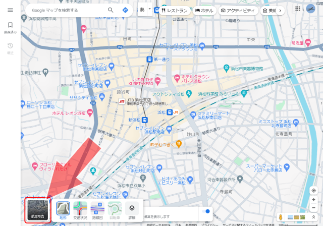 Find the scenery or building you want to create on Google Maps.
Then click the "Satellite Image" button at the bottom left of the screen.
Find the scenery or building you want to create on Google Maps.
Then click the "Satellite Image" button at the bottom left of the screen.
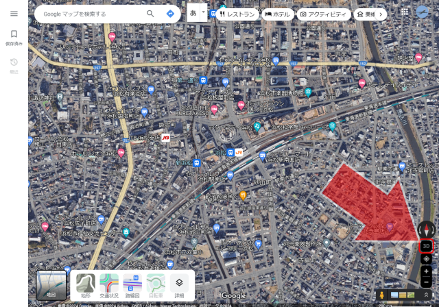 Click the "3D" button at the bottom right of the satellite photo screen.
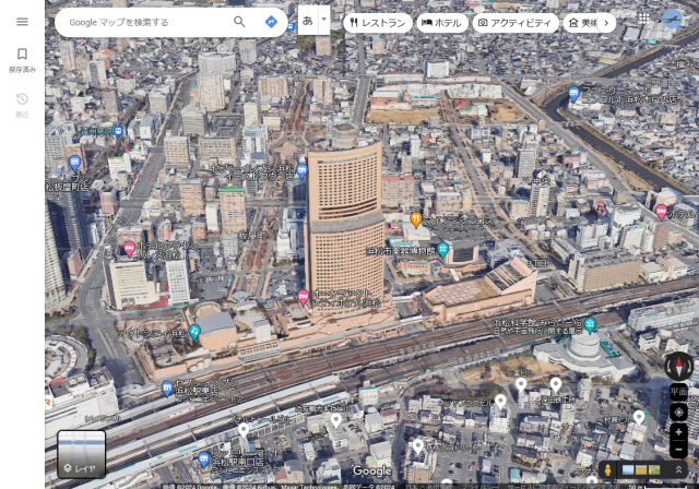 Once the scenery and buildings are displayed in 3D, you can use the Google Earth Decoder to convert the 3D data for that location into MSFS format.
In areas where 3D data is not supported, the satellite imagery will simply be displayed tilted, and the buildings will not be displayed in 3D.
Once the scenery and buildings are displayed in 3D, you can use the Google Earth Decoder to convert the 3D data for that location into MSFS format.
In areas where 3D data is not supported, the satellite imagery will simply be displayed tilted, and the buildings will not be displayed in 3D.
On this screen, you can move the viewpoint by holding down the [Ctrl] key and moving the mouse. You can zoom in and out by turning the mouse scroll wheel.
If you want to convert a large area into MSFS format, make sure to check the range of areas that are supported for 3D data.
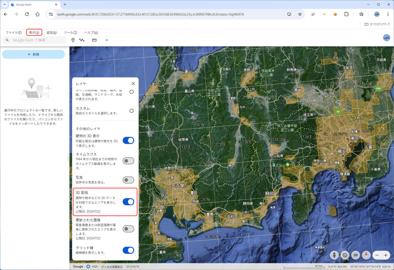 Or, open
Google Earth
in your browser, select [View]-[Layers] from the menu, and turn on "3D Building Display" in the dialog box that appears.
Then, the areas for which 3D data is available will be filled in orange, as shown in the image on the right.
However, the fill is only visible from a high vantage point.
Or, open
Google Earth
in your browser, select [View]-[Layers] from the menu, and turn on "3D Building Display" in the dialog box that appears.
Then, the areas for which 3D data is available will be filled in orange, as shown in the image on the right.
However, the fill is only visible from a high vantage point.
Google Earth
Installation of various development tools
To create add-on content for Microsoft Flight Simulator, first install various tools on your computer.
Please refer to the page below.
Naming the package and creating the project
Think about the package name of the scenery you want to create.
MSFS SDK has strict package naming rules.
Think about a correct package name that follows the rules.
Once you have decided on the package name, create an empty project. If you are using the Google Earth Decoder, I recommend creating a scenery project using the Blender plugin "Google Earth Decoder Optimization Tools (GEDOT)".
Please refer to the page below.
Download 3D data with Google Earth Decoder
Once you have an empty project ready, download the Google Earth 3D data into it.
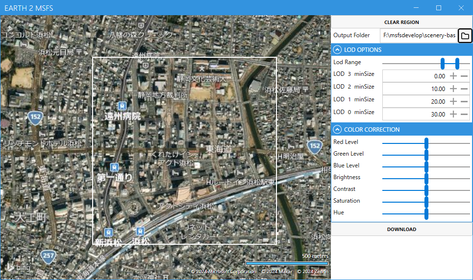 Double-click "Earth2MsfsWPF.exe" in the Google Earth Decoder folder to launch Google Earth Decoder.
In the "Output Folder" field in the upper right corner of the screen, click the folder icon to specify the folder to save the 3D data in. If you have an empty project, specify the "PackageSources" folder in it.
In the "LOD OPTIONS" field, specify the range of the Level Of Details (LOD) of the data to be downloaded. Drag the two blue bars left and right to specify the minimum and maximum LOD. The smaller the number, the lower the detail (less data volume), and the larger the number, the higher the detail (more data volume).
The default values for each minSize field in this screen are incorrect, but they will be automatically corrected if you optimize the scenery data . It's fine to leave it as it is.
In the "COLOR CORRECTION" field, you can adjust the color tone, etc of the texture. The downloaded texture is a bit too bright, so it may be a good idea to set only the Brightness to around 0.9. However, since you cannot check the color in real time on this screen, it may be difficult to use this function. If color adjustment is required, please process the texture file directly with a paint tool such as GIMP after completing the scenery.
Adjust brightness and color of textures/Batch process multiple images at once
While on the map, you can zoom in and out by using the mouse scroll wheel or double-clicking the left button.
You can move the location by dragging.
You can select the area to download 3D data by dragging the mouse while holding down the right button. A white rubber band will be displayed. You can drag repeatedly to reselect the range as many times as you like. However, 3D data is downloaded in units of "tiles" defined by Google Earth. Therefore, data for an area larger than the area enclosed by the white line will actually be downloaded.
Click the "CLEAR REGION" button in the upper right corner of the screen to clear the selected region. You can then select the region again.
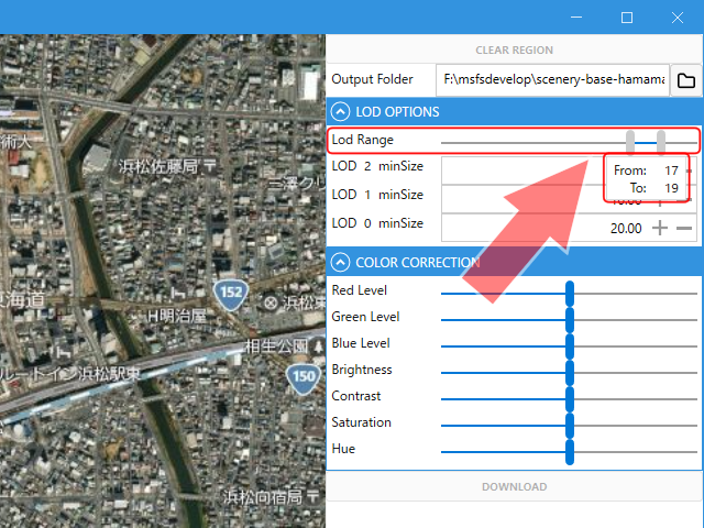 Specifying a larger LOD will display a more detailed scenery, but will slow down the game speed (FPS value).
Normally, specify a minimum LOD value of 17 and a maximum of 19.
Specifying a larger LOD will display a more detailed scenery, but will slow down the game speed (FPS value).
Normally, specify a minimum LOD value of 17 and a maximum of 19.
The data size of LOD20 can be more than 10 times the data size of all LOD17-19. If you are creating scenery that will be enlarged in-game, such as an airport building, try narrowing the range very much and setting the maximum LOD to 20 or 21. Note that specifying LOD 22 or higher may cause an error in the MSFS build due to the amount of data being too large. Do not specify LOD 22 or higher.
If you are creating scenery that will be zoomed in during gameplay, such as an airport, try setting the maximum LOD to 20 or 21 with a very narrow range. Also, if you specify the maximum LOD22, an error may occur during the MSFS build, possibly due to the amount of data being too large.
In urban areas with many buildings, even a maximum LOD of 19 may not provide a practical game speed. In such cases, narrow the range or lower the maximum LOD.
It may be a good idea to create separate scenery for the entire area and the landmark buildings within it, specify individual maximum LOD values for each, and then merge those scenery datas later.
What is minSize?
minSize (unit: %) is an indicator used to select the resolution of objects in the game. When the size of an object on the game screen becomes larger than the minSize value, the model of that LOD will be displayed. If this is not set correctly, a low resolution model will be displayed even if you approach the object, or a high resolution model will be displayed even if you move away from the object. It needs to be adjusted each time according to the size of the object (the size of the downloaded Google Map). Optimizing scenery data splits the scenery into tiles and sets the correct minSize.
For more information about LODs, see the following pages of the MSFS SDK documentation.
LOD SELECTION SYSTEM (MSFS 2024 SDK Documentation)
LODs (MSFS SDK Documentation)
 If the contents of your project's PackageSources folder exceed 7.5GB, an error may occur when building with MSFS.
If you select an area that is too large, the build will fail.
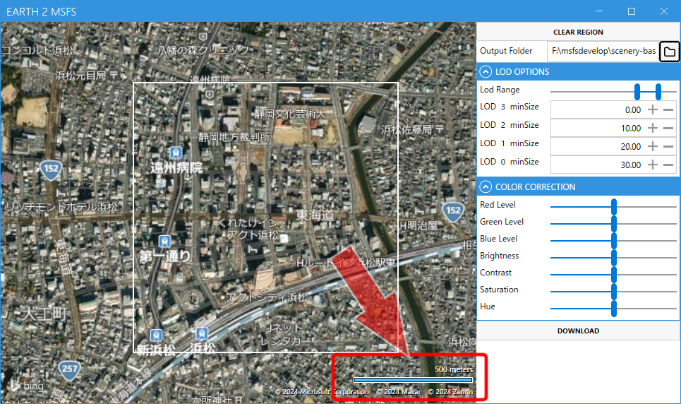
If you specify LOD 17-19, please refer to the gauge at the bottom right of the screen and first select an area of about 5-6 km square to check the amount of data to be downloaded.
If the contents of your project's PackageSources folder exceed 7.5GB, an error may occur when building with MSFS.
If you select an area that is too large, the build will fail.
If you specify LOD 17-19, please refer to the gauge at the bottom right of the screen and first select an area of about 5-6 km square to check the amount of data to be downloaded.
If you create a wide-area scenery at once, the tiles on the edge of the scenery may sink into the ground of MSFS. If you want to create a wide-area scenery, it is better to create it in parts of about 2~3km square, and then merge those scenery datas at the end.
In the example on the right, an area of approximately 1km (0.6mi) square is selected, and the number of tiles that will be downloaded will be 4.
When using Google Earth Decoder for the first time, please test it in a very small area to ensure that each installed tool works properly,
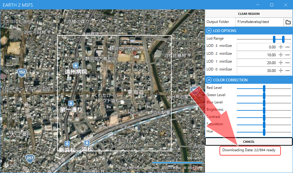 Once you have completed the settings, click the "DOWNLOAD" button.
This will start downloading the 3D data.
Once you have completed the settings, click the "DOWNLOAD" button.
This will start downloading the 3D data.
If you want to cancel the download, click the "CANCEL" button.
Please note that for various reasons, the download may not start even when you click the "DOWNLOAD" button. If this happens, try reducing the area, changing the location, or waiting a while before trying again. Downloading will not start in areas where 3D data is not supported.
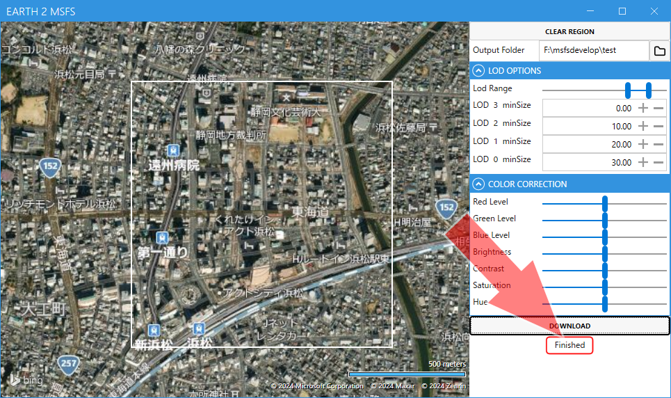 When the download is complete, "Finished" will be displayed under the "DOWNLOAD" button.
Two folders named "modelLib" and "scene" should be created under the specified folder.
The 3D scenery data is stored in these folders.
Make sure total data volume does not exceed 7.5GB.
When the download is complete, "Finished" will be displayed under the "DOWNLOAD" button.
Two folders named "modelLib" and "scene" should be created under the specified folder.
The 3D scenery data is stored in these folders.
Make sure total data volume does not exceed 7.5GB.
We compared how much the appearance changes in-game depending on the maximum LOD specified. These images show models with maximum LODs of 21, 20, and 19, viewed from the same location. The amount of data is more than three times larger between each LOD.


Optimize scenery data
The Blender plugin Google Earth Decoder Optimization Tools (GEDOT) allows you to optimize the downloaded scenery data.
Note: Google Earth Decoder Optimization Tools (GEDOT) must be used with Blender versions 3.5. The GEDOT used on this page is version 1.1.3 (April 2022 version).
Google Earth Decoder Optimization Tools (flightsim.to)
Google Earth Decoder Optimization Tools (Github)
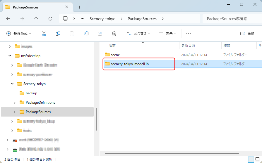 In GEDOT, the name of the ModelLib asset group is defined as "[package name]-modelLib".
Change the name of the "modelLib" folder generated by Google Earth Decoder to match this.
In GEDOT, the name of the ModelLib asset group is defined as "[package name]-modelLib".
Change the name of the "modelLib" folder generated by Google Earth Decoder to match this.
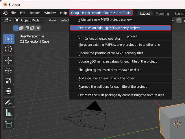 Start Blender and select [Google Earth Decoder Optimization Tools]-[Optimize an existing MSFS scenery project] from the menu.
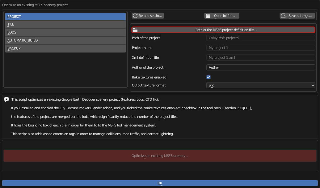 A dialog box like this will appear.
Click on the part that says Path of the MSFS projects... in the top center of the screen.
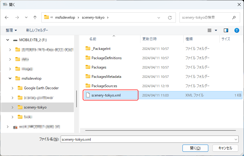
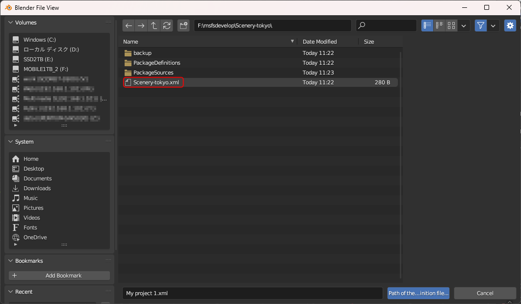 A file selection screen will appear, so select "Scenery-[scenery name].xml" located directly under the project folder.
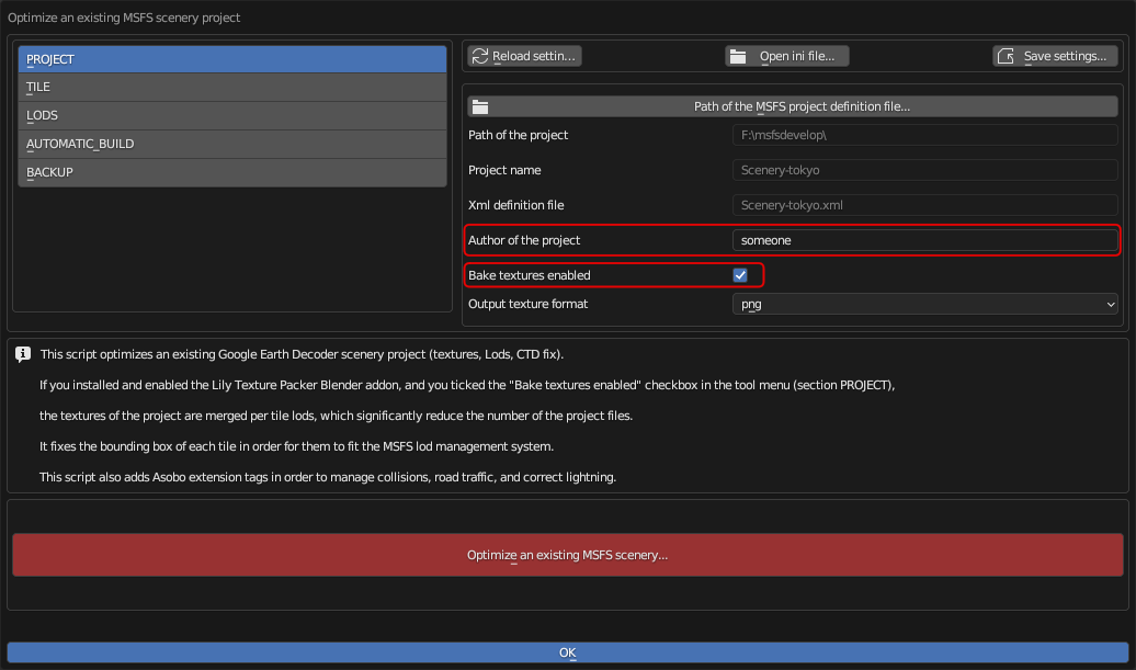 The project information will then be reflected on the screen.
Please make sure that the items in the "Path of the project", "Project name", and "Xml definition file" columns are loaded correctly.
The project information will then be reflected on the screen.
Please make sure that the items in the "Path of the project", "Project name", and "Xml definition file" columns are loaded correctly.
In the Author of the project field, specify your name/pen name etc. (in this example, "someone").
If you check Bake texutures enabled, the textures for each LOD of each tile that makes up the ground will be composited into one. This will improve the game's display speed (FPS value). However, to use this function, you must have the Lily Texture Packer plug-in installed in Blender. For instructions on how to install Lily Texture Packer, see below.
How to download and install MSFS SDK, Blender, plugin, tools
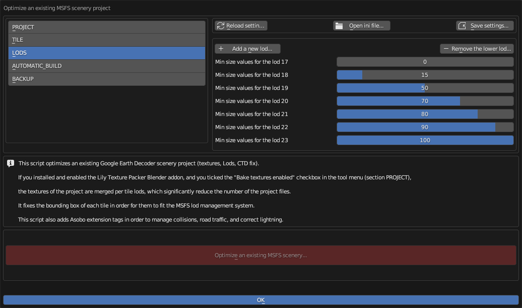 If you select [LODS] from the menu on the left side of the screen, you will see the screen shown on the right.
On this screen, you specify the "minSize" value for each LOD value. The correct value is set by default, so no updating is required.
However, this screen only has setting values from LOD17 to LOD23. If there is data with lower or higher LOD values, it will need to be added and corrected.
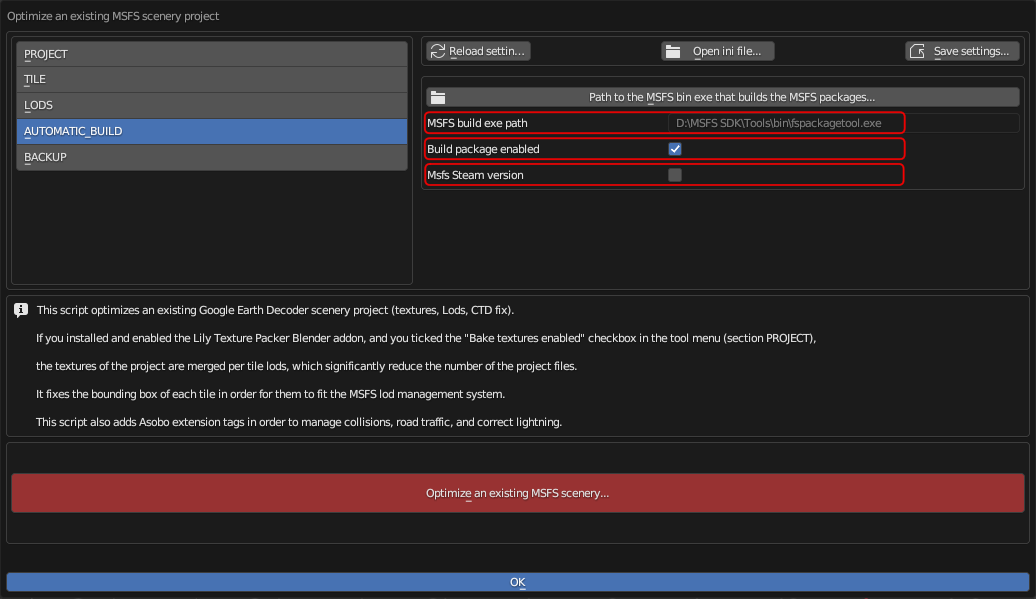 If you select [AUTOMATIC_BUILD] from the menu on the left side of the screen, you will see the screen shown on the right.
Click on the "Path of the MSFS bin exe..." in the top center of the screen to open the folder selection screen. Here, specify the location of the MSFS SDK build tool "fspackagetool.exe". This is usually located under "[MSFS SDK installation folder]\Tools\bin".
If you check Build package enabled, the build will start automatically after optimization is complete.
Also, if the MSFS you purchased is the Steam version, please check MSFS Steam version.
Finally, click the red [Optimize an existing MSFS scenery...] button to begin optimizing your project.
Clicking the blue [OK] button will close this dialog box.
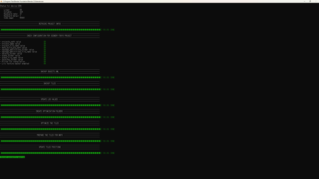 While the optimization is in progress, you will see a screen like the one shown here.
When you see "Script correctly applied," the optimization is complete.
While the optimization is in progress, you will see a screen like the one shown here.
When you see "Script correctly applied," the optimization is complete.
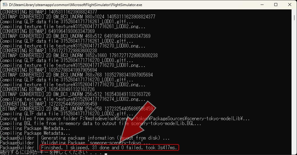 If you have checked "Build package enabled", wait about 20~30 seconds and the MSFS "fspackagetool.exe" will launch and the build will begin.
When you see the message "Press any key to continue...", the build is complete.
Make sure that no errors are displayed on the screen.
Also, make sure that "0 failed" is displayed at the bottom of the screen.
If you have checked "Build package enabled", wait about 20~30 seconds and the MSFS "fspackagetool.exe" will launch and the build will begin.
When you see the message "Press any key to continue...", the build is complete.
Make sure that no errors are displayed on the screen.
Also, make sure that "0 failed" is displayed at the bottom of the screen.
If you get an error here, please refer to the How to download and install MSFS SDK, Blender, plugin, tools page to make sure you have the appropriate version of each tool.
How to download and install MSFS SDK, Blender, plugin, tools
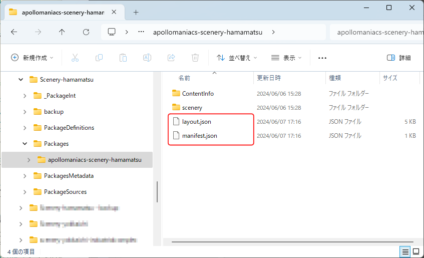 Also, if "layout.json" and "manifest.json" are not generated under the [Packages]-[(package name)] folder in the project folder, the build has failed.
If the amount of data is too large, the build may crash during the process.
Try narrowing the range of the scenery.
Also, if "layout.json" and "manifest.json" are not generated under the [Packages]-[(package name)] folder in the project folder, the build has failed.
If the amount of data is too large, the build may crash during the process.
Try narrowing the range of the scenery.
If you want to create scenery for a larger area, you will need to split it into multiple projects.
 If the build is successful, check the current state on the MSFS game screen.
For instructions on how to check, see
Check the project build result on the game screen
.
If the build is successful, check the current state on the MSFS game screen.
For instructions on how to check, see
Check the project build result on the game screen
.
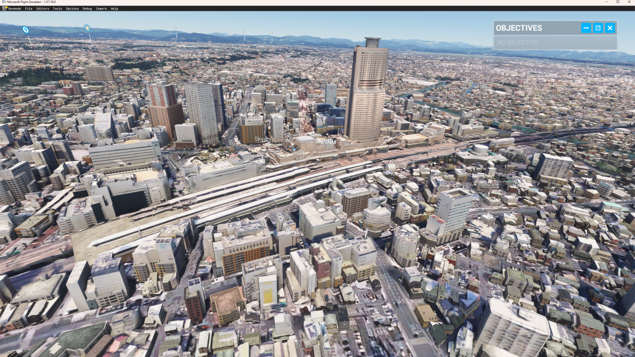
As shown on the right, the 3D data loaded from Google Earth is displayed on the game screen. However, if you look closely at the small buildings in the foreground and at the back center, you will see that the buildings loaded from Google Earth and buildings automatically generated by MSFS are overlapping each other. Next, add an "Exclude polygon" to the scenery to remove these automatically generated buildings.
Check the project build result on the game screen
Preparing the scenery for processing: Grouping objects
Let's load the Google Maps scenery you created into the MSFS SDK and prepare it for processing.
Organize the Google Maps objects into "groups."
★This step is not required. It just makes it easier to use when modifying packages with the MSFS SDK.
 Start MSFS and load the built project into the SDK.
See
Check the project build result on the game screen
for instructions on how to do this.
Start MSFS and load the built project into the SDK.
See
Check the project build result on the game screen
for instructions on how to do this.
Check the project build result on the game screen
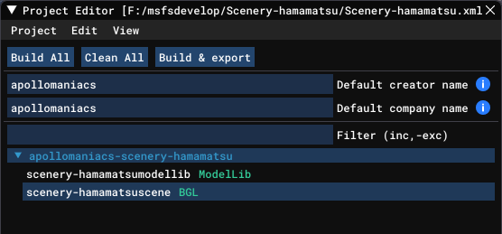
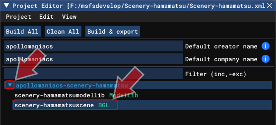 Once you've loaded the project into the SDK, click the triangle mark to the left of the package name on the Project Editor screen.
This will display a list of asset groups included in the package.
Click on the asset group "BGL" from there.
Once you've loaded the project into the SDK, click the triangle mark to the left of the package name on the Project Editor screen.
This will display a list of asset groups included in the package.
Click on the asset group "BGL" from there.
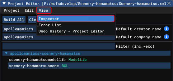 Next, select [View]-[Inspector] from the Project Editor menu.
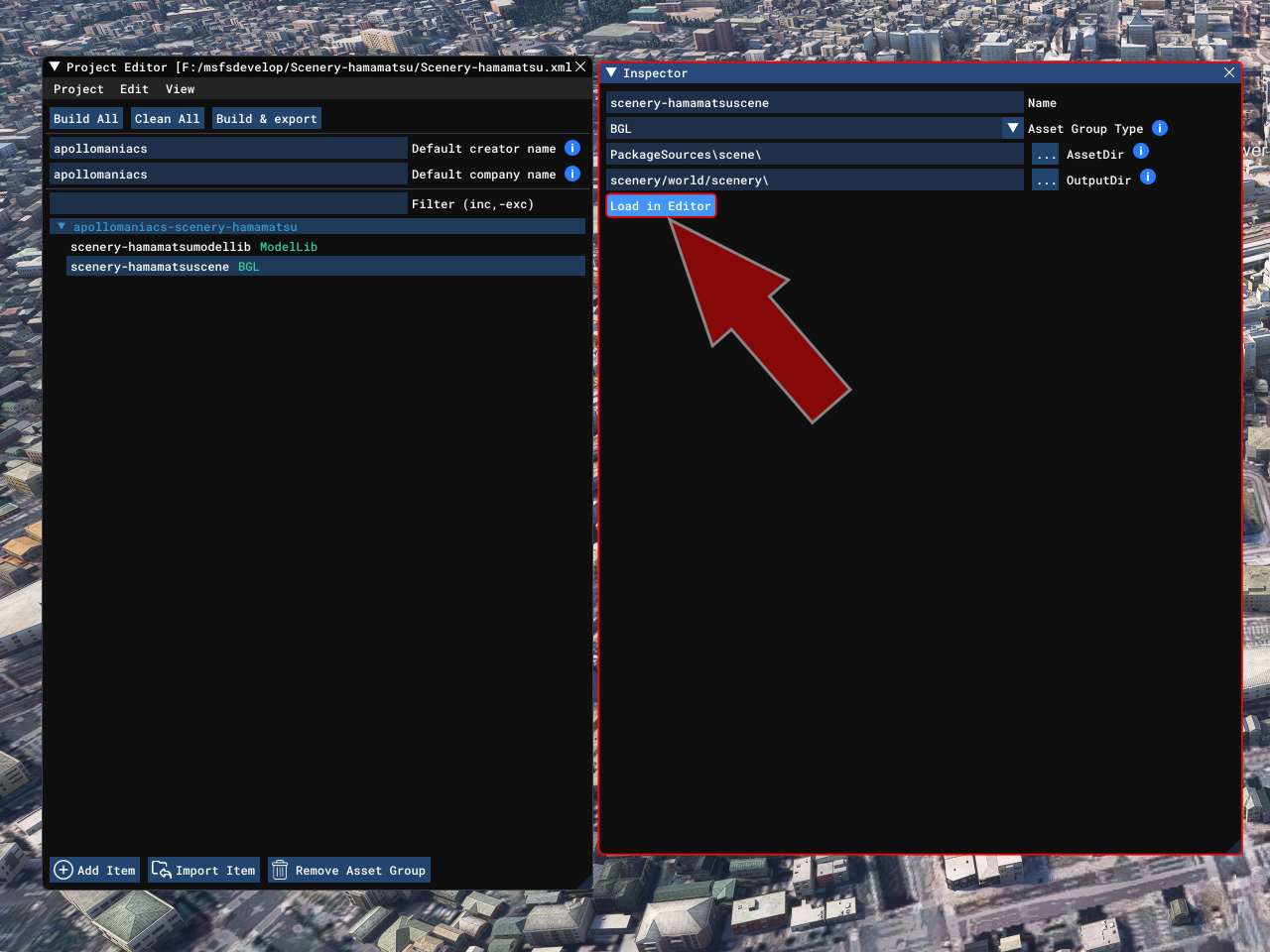 This will open the Inspector screen as shown on the right.
Click [Load in Editor].
This will open the Inspector screen as shown on the right.
Click [Load in Editor].
Attention:
Please note that if you do not advance to the WORLD MAP screen until the [READY TO FLY] button is displayed in the bottom right corner of the screen (Identifying the location of the simulation), an error will occur here.
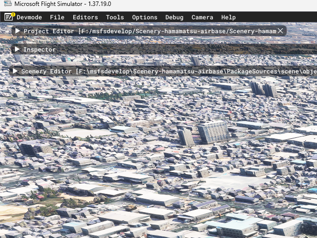 [FYI]
[FYI]As you use the Developer menu, new windows will open one after another. Rearrange the windows as needed to make it easier to use.
Alternatively, you can collapse the window as shown here by clicking the "▼" mark in the upper left corner of each window, to the left of the window name.
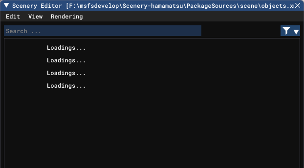 The Scenery Editor screen will then open and the scenery data will begin loading.
Wait a while until the "Loadings..." message disappears.
The Scenery Editor screen will then open and the scenery data will begin loading.
Wait a while until the "Loadings..." message disappears.
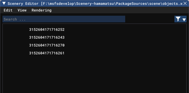 Once loading is complete, a list of objects included in the scenery will be displayed, as shown on the right.
In this example, the 3D data of Google Maps is stored divided into four tiles.
Once loading is complete, a list of objects included in the scenery will be displayed, as shown on the right.
In this example, the 3D data of Google Maps is stored divided into four tiles.
At this point, the Google Maps scenery data has been loaded into the MSFS SDK. You can use the SDK to edit the scenery or add new objects.
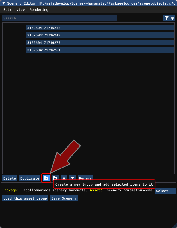 Before adding a new object, group the 3D data from Google Maps into one.
Hold down the [Ctrl] key and click on the Google Maps tiles to select them all.
Then click the
Before adding a new object, group the 3D data from Google Maps into one.
Hold down the [Ctrl] key and click on the Google Maps tiles to select them all.
Then click the
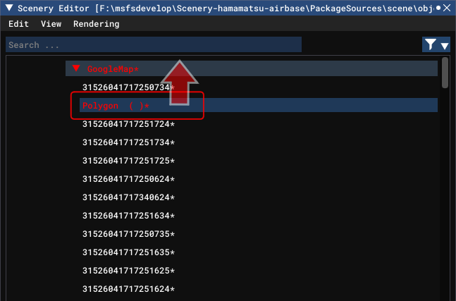
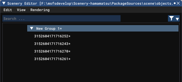 A new "New Group 1" was immediately generated and the Google Maps tiles were placed in it.
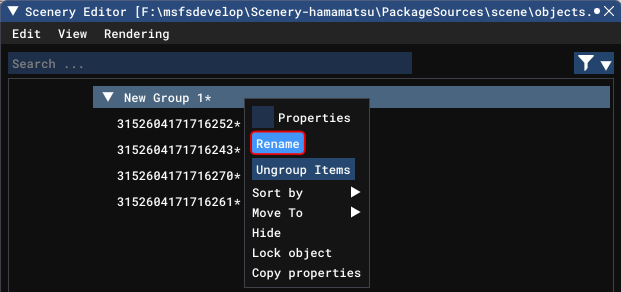 If you right-click on the group name, a dialog box like this will appear.
You can change the group name by clicking the "Rename" button.
If you right-click on the group name, a dialog box like this will appear.
You can change the group name by clicking the "Rename" button.
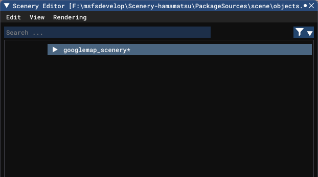 This time I changed the group name to "googlemap_scenery".
Create an Exclude polygon to remove MSFS auto-generated buildings
By placing an "Exclude polygon" in the scenery you created, you can remove buildings automatically generated by MSFS.
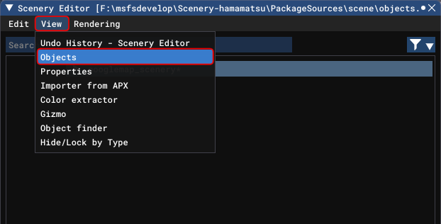 Open the "Objects" screen to select a new object to add.
Select [View]-[Objects] from the Scenery Editor screen menu.
Open the "Objects" screen to select a new object to add.
Select [View]-[Objects] from the Scenery Editor screen menu.
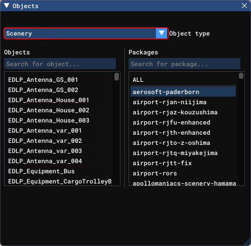 The Objects screen opens.
Initially, "Scenery" is selected in the "Object Type" column.
The Objects screen opens.
Initially, "Scenery" is selected in the "Object Type" column.
In this state, you can copy and bring in objects from all the scenery you have installed in MSFS. You can import objects developed by other users into your scenery.
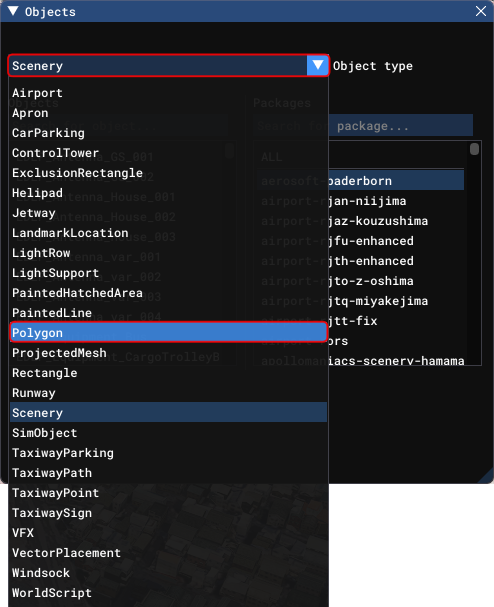 Since what you are adding to the scenery here is a polygon, click the "Object Type" field and select "Polygon".
For more information about the objects that can be handled by MSFS, see the following pages of the MSFS SDK documentation.
SCENERY OBJECTS (MSFS 2024 SDK Documentation)
OBJECTS (MSFS SDK Documentation)
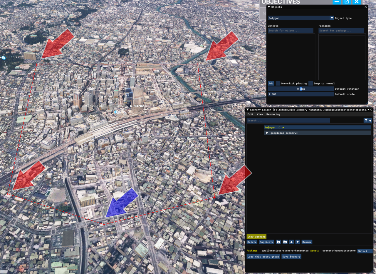
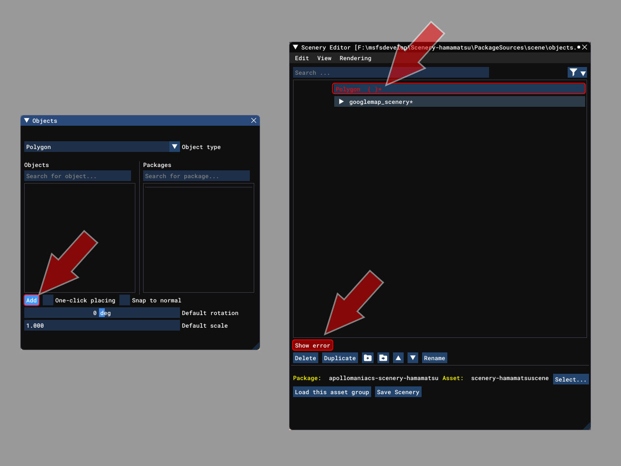 Next, click the [Add] button on the Objects screen (left side of the image).
This will add a "Polygon" in red to the Scenery Editor screen (top right side of the image).
As this polygon does not yet have any vertices, it cannot be displayed on the game screen.
As a result, "Show error" is displayed in red (bottom right side of the image).
Next, click the [Add] button on the Objects screen (left side of the image).
This will add a "Polygon" in red to the Scenery Editor screen (top right side of the image).
As this polygon does not yet have any vertices, it cannot be displayed on the game screen.
As a result, "Show error" is displayed in red (bottom right side of the image).
 If the polygon has been generated inside a Google Maps tile group, drag and drop it outside the group.
 First, roughly place the vertices of a polygon to surround the Google Maps scenery you have created.
On the Scenery Editor screen, click the red "Polygon" you added to select it.
Next, hold down the [Ctrl] key and left-click the mouse on the game screen to add a vertex (red arrow in the right image). Continue clicking with [Ctrl] to surround the scenery. Then, without pressing the [Ctrl] key, double-click the left mouse button to finish adding a vertex. However, a vertex will not be placed where you double-clicked (blue arrow in the image).
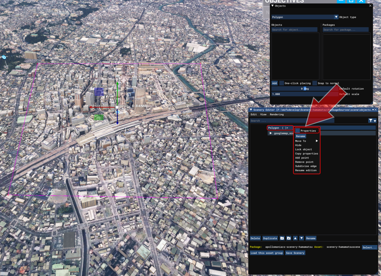 It's hard to see in the image, but the completed polygons are connected by purple lines.
You'll specify this polygon as the "Exclude polygon".
On the Scenery Editor screen, right-click on the "Polygon" we just added and a menu like the one on the right will appear.
Click the box to the left of "Properties".
It's hard to see in the image, but the completed polygons are connected by purple lines.
You'll specify this polygon as the "Exclude polygon".
On the Scenery Editor screen, right-click on the "Polygon" we just added and a menu like the one on the right will appear.
Click the box to the left of "Properties".
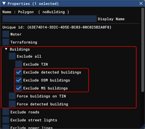 The polygon properties screen will be displayed.
Click "Buildings" to expand it and check "Exclude all".
The automatically generated buildings inside the polygon will then disappear.
The polygon properties screen will be displayed.
Click "Buildings" to expand it and check "Exclude all".
The automatically generated buildings inside the polygon will then disappear.
"TIN" is a photogrammetry generated building from Bing Maps (Triangulated Irregular Network).
"detected buildings" are buildings synthesized from satellite images.
"OSM buildings" are buildings based on Open Street Map .
"MS buildings" are buildings created by Microsoft's automatic building generation AI (Blackshark.ai).
For more information about polygons, how to manipulate them, and their properties, see the following pages of the MSFS SDK documentation.
OSM buildings (Open Street Map)
POLYGON OBJECTS (MSFS 2024 SDK Documentation)
POLYGON OBJECTS (MSFS SDK Documentation)
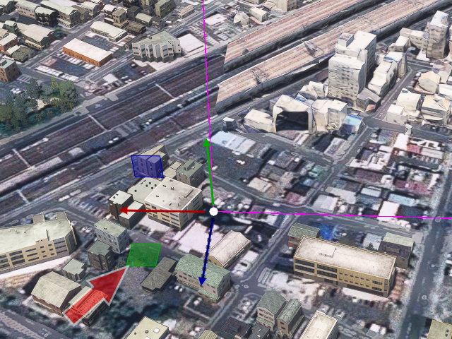 Next, fine-tune the position of each vertex of the polygon.
With the "Polygon" you just added selected in the Scenery Editor screen, click any vertex on the screen to display a handle like the one shown on the right.
Now, you can move the vertex only on the horizontal plane by dragging the green square indicated by the arrow in the image.
Adjust each vertex so that it perfectly surrounds the Google Maps scenery.
Next, fine-tune the position of each vertex of the polygon.
With the "Polygon" you just added selected in the Scenery Editor screen, click any vertex on the screen to display a handle like the one shown on the right.
Now, you can move the vertex only on the horizontal plane by dragging the green square indicated by the arrow in the image.
Adjust each vertex so that it perfectly surrounds the Google Maps scenery.
Switching the camera to "Top Down Camera" will give you a top-down view, allowing for more precise alignment.
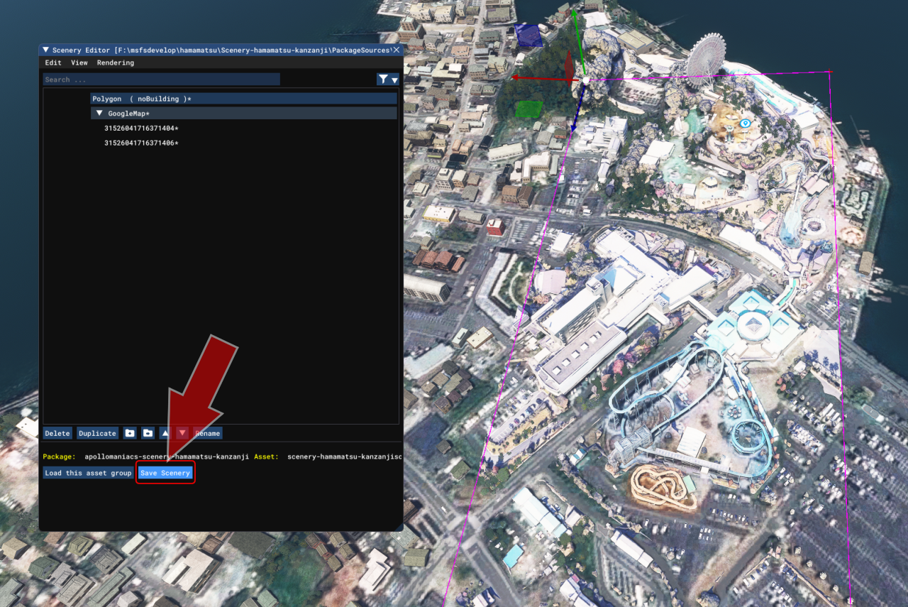
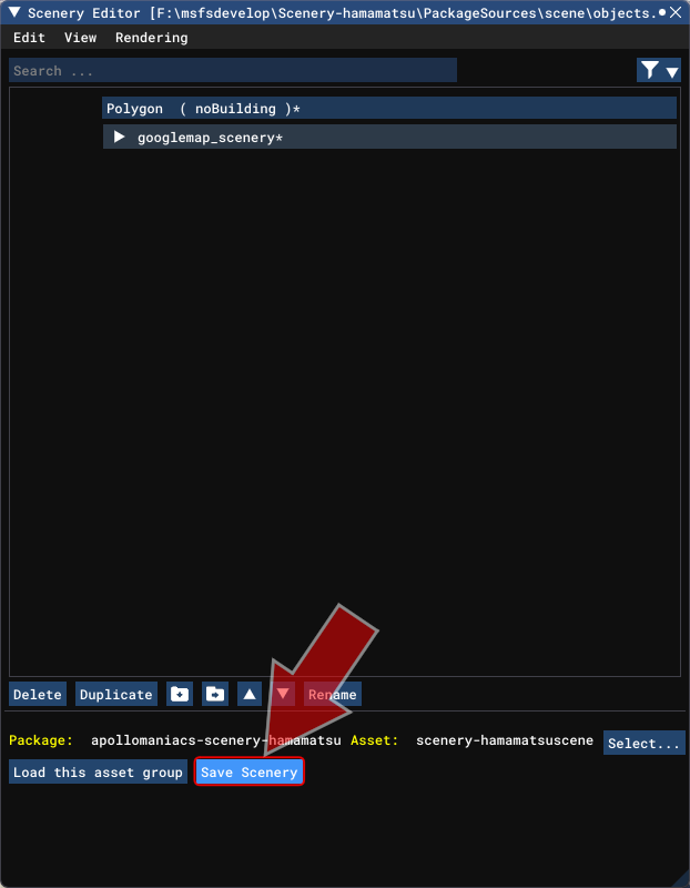 Once you have completed the Exclude polygon, click the [Save Scenery] button at the bottom of the Scenery Editor screen to save the scenery.
Note: If you close the Scenery Editor screen here, the Google Maps scenery you created will disappear from the game screen. However, it will remain in the project, so if you select BGL in the Project Editor screen and click the [Load in Editor] button in the Inspector screen, the scenery will return to the game screen.
 Before building, set the version number of your package.
Whenever you make improvements to the content you are releasing, you should increase the version number.
Before building, set the version number of your package.
Whenever you make improvements to the content you are releasing, you should increase the version number.
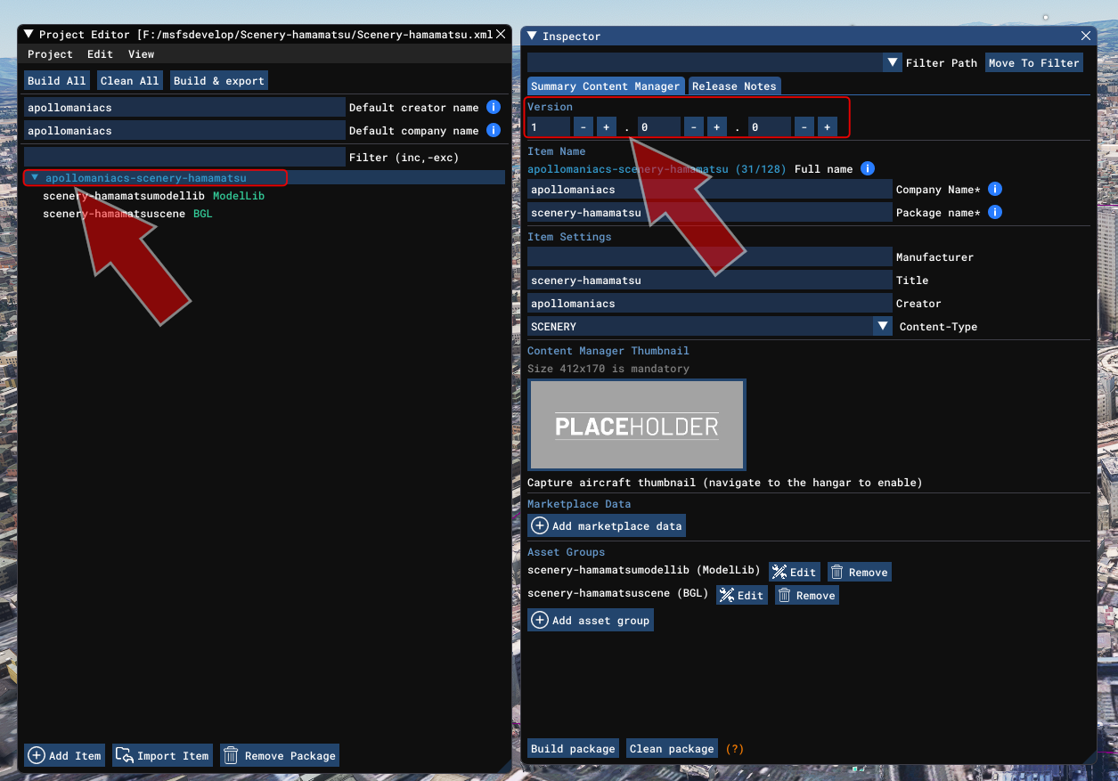
Click the package name to select it on the Project Editor screen, then select [View]-[Inspector] from the Project Editor menu. A field for entering the version number will then appear on the Inspector screen.
The version number consists of three numbers, from the left are the major version, minor version, and patch version. For minor fixes, you should increase the patch version. When you add features, you should increase the minor version. When you make major modifications, you should increase the major version.
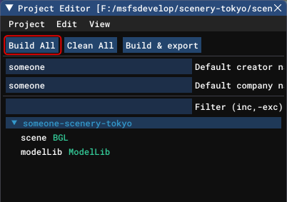 Finally, build the project with the MSFS SDK to complete it.
Clicking the [Clean All] button on the Project Editor screen will delete old packages under the "Packages" folder.
Next, click the [Build All] button to start the build.
Finally, build the project with the MSFS SDK to complete it.
Clicking the [Clean All] button on the Project Editor screen will delete old packages under the "Packages" folder.
Next, click the [Build All] button to start the build.
For detailed instructions on building a project, see the "Build the project" chapter in How to create a project for MSFS add-on content .
How to create a project for MSFS add-on content
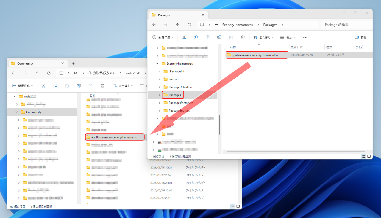 If the build is successful, a folder with the package name will be created under the Packages folder.
Copy this to the "Community" folder in the MSFS data storage folder and it will be installed on your MSFS.
When you want to distribute the package, compress this folder and upload it to a distribution site etc.
If the build is successful, a folder with the package name will be created under the Packages folder.
Copy this to the "Community" folder in the MSFS data storage folder and it will be installed on your MSFS.
When you want to distribute the package, compress this folder and upload it to a distribution site etc.
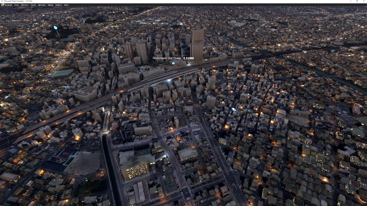 Restart MSFS and start the game. The Google Maps scenery you created will appear in the game.
If you have optimized the scenery with GEDOT, automatically generated cars (traffic) will run on the roads.
If you switch the time to night, the street lights will also turn on.
Since collision detection is enabled, if the plane collides with a building, it will crash without going through.
However, the windows of the building will remain dark in the night.
Restart MSFS and start the game. The Google Maps scenery you created will appear in the game.
If you have optimized the scenery with GEDOT, automatically generated cars (traffic) will run on the roads.
If you switch the time to night, the street lights will also turn on.
Since collision detection is enabled, if the plane collides with a building, it will crash without going through.
However, the windows of the building will remain dark in the night.
You can add more realism to major buildings by placing lights that illuminate the entire building, and by placing red flashing lights (Aviation Obstruction Lights) on high-rise buildings.
Where polygon objects are stored
The polygon information added to the scenery using the steps above will be added and saved in the "objects.xml" file under the "PackageSources\scene" folder.
Adding lights to the scenery

Another way to combine these techniques is to export Blender light objects as parts and place them in large quantities within the MSFS SDK.
For information on these methods, see the page How to add lights/illumination to MSFS scenery .
How to add lights/illumination to MSFS scenerys
Adding moving smoke, fire, fog, water, etc. to the scenery

For information on these methods, see the page How to add moving smoke, fire, fog, water, etc. to MSFS scenery / How to use Visual Effect Editor .
How to add moving smoke, fire, fog, water, etc. to MSFS scenery / How to use Visual Effect Editor
Compress DDS textures to reduce package size
The texture files will be converted to DDS format and stored in the release package of the MSFS scenery you developed.
By using the Blender plugin Google Earth Decoder Optimization Tools (GEDOT) and the graphics-related tool Compressonator, which is openly developed under the auspices of AMD,
you can compress the size of these DDS format texture files to less than half.
This will reduce the size of the package when distributed and reduce the load during gameplay.
The best time to compress textures is after the scenery is complete and the final build is finished, just before releasing the package.
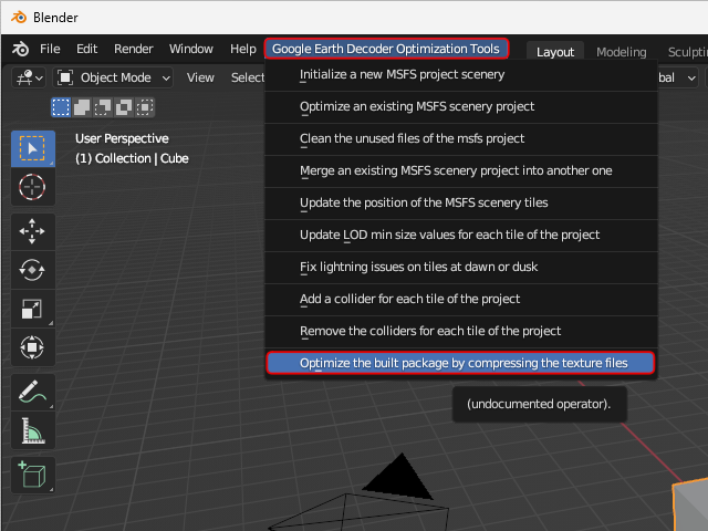 Start Blender and select [Google Earth Decoder Optimization Tools]-[Optimize the built package by compressing the texture files] from the menu.
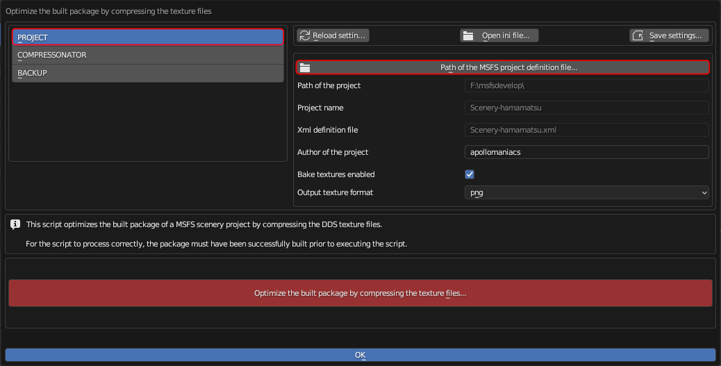 First, select [PROJECT] from the menu on the left side of the screen.
Just like when
optimizing scenery data
, click on the "Path of the MSFS projects..." section in the top center of the screen to load the scenery information to be compressed.
Then enter the name of the developer (you) in the "Author of the project" field.
First, select [PROJECT] from the menu on the left side of the screen.
Just like when
optimizing scenery data
, click on the "Path of the MSFS projects..." section in the top center of the screen to load the scenery information to be compressed.
Then enter the name of the developer (you) in the "Author of the project" field.
The scenery to be compressed must have been successfully built with MSFS SDK in advance.
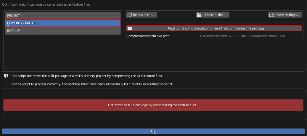 Next, select [COMPRESSONATOR] from the menu on the left side of the screen.
Click on the "Path to the compressonator bin exe..." section in the top center of the screen and specify the installation folder for "compressonatorcli.exe".
Compressonator is installed in "C: \Compressonator_[Version] \bin \CLI \compressonatorcli.exe".
Next, select [COMPRESSONATOR] from the menu on the left side of the screen.
Click on the "Path to the compressonator bin exe..." section in the top center of the screen and specify the installation folder for "compressonatorcli.exe".
Compressonator is installed in "C: \Compressonator_[Version] \bin \CLI \compressonatorcli.exe".
Finally, click the red [Optimize the built package by...] button to start compressing the texture.
Clicking the blue [OK] button will close this dialog box.
For instructions on how to install Compressonator, please see below.
How to download and install MSFS SDK, Blender, plugin, tools
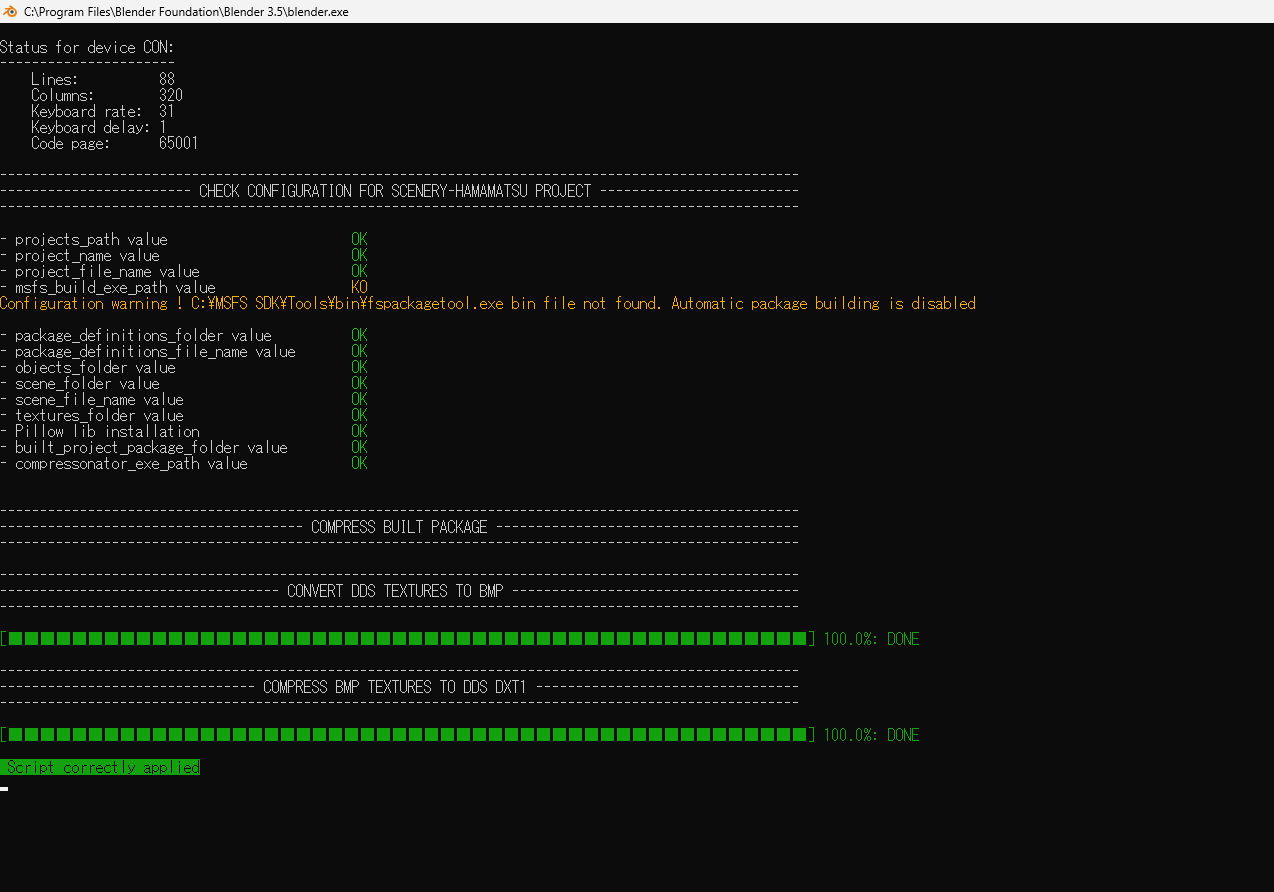 While the compression is in progress, you will see a screen like this.
When you see "Script correctly applied" it's complete.
While the compression is in progress, you will see a screen like this.
When you see "Script correctly applied" it's complete.
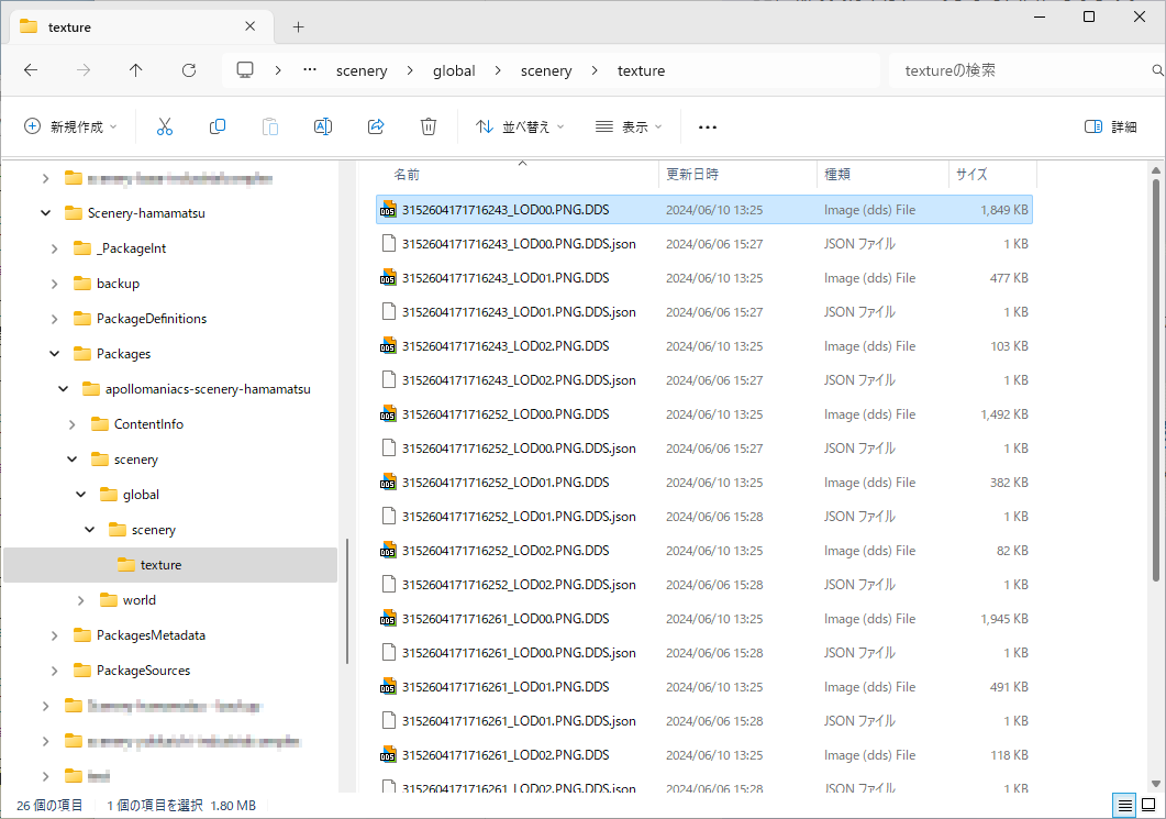 The storage folder for textures to be compressed is:
"[Project Folder] \Packages \[Package Name] \scenery \global \scenery \texture"
The storage folder for textures to be compressed is:
"[Project Folder] \Packages \[Package Name] \scenery \global \scenery \texture"
Comparing before and after compression, in this example, the total size of the contents of the "texture" folder was reduced from 22.4MB to 8.45MB. Compressed to nearly one-third of the original file size.
Check the project build result on the game screen
Here we will explain how to load the built project under development into the MSFS SDK and check it on the game screen.
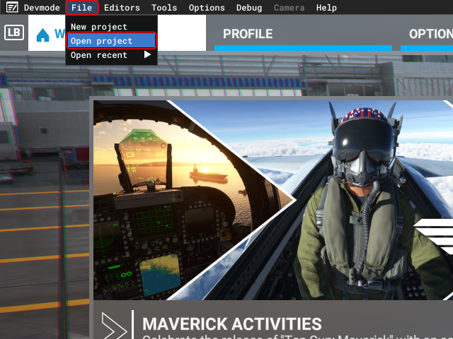 Start MSFS and select [File]-[Open project] from the developer menu.
Alternatively, you can select [Open recent] below to choose from a list of recently opened projects.
 A file selection dialog box will then appear, so select the "[package name].xml" file located directly under the project folder.
Note that if you create multiple packages in one project, multiple "[package name].xml" files will be generated here.
 Then the Project Editor screen will open, as shown in the figure.
You cannot move to the simulation screen unless the project has been [Save] in MSFS SDK. After loading, first select [Project]-[Save]. If the [Save] menu is grayed out, the project has already been saved.
 Leave the Project Editor screen as is.
If it gets in the way of your work, move it to the side.
Leave the Project Editor screen as is.
If it gets in the way of your work, move it to the side.
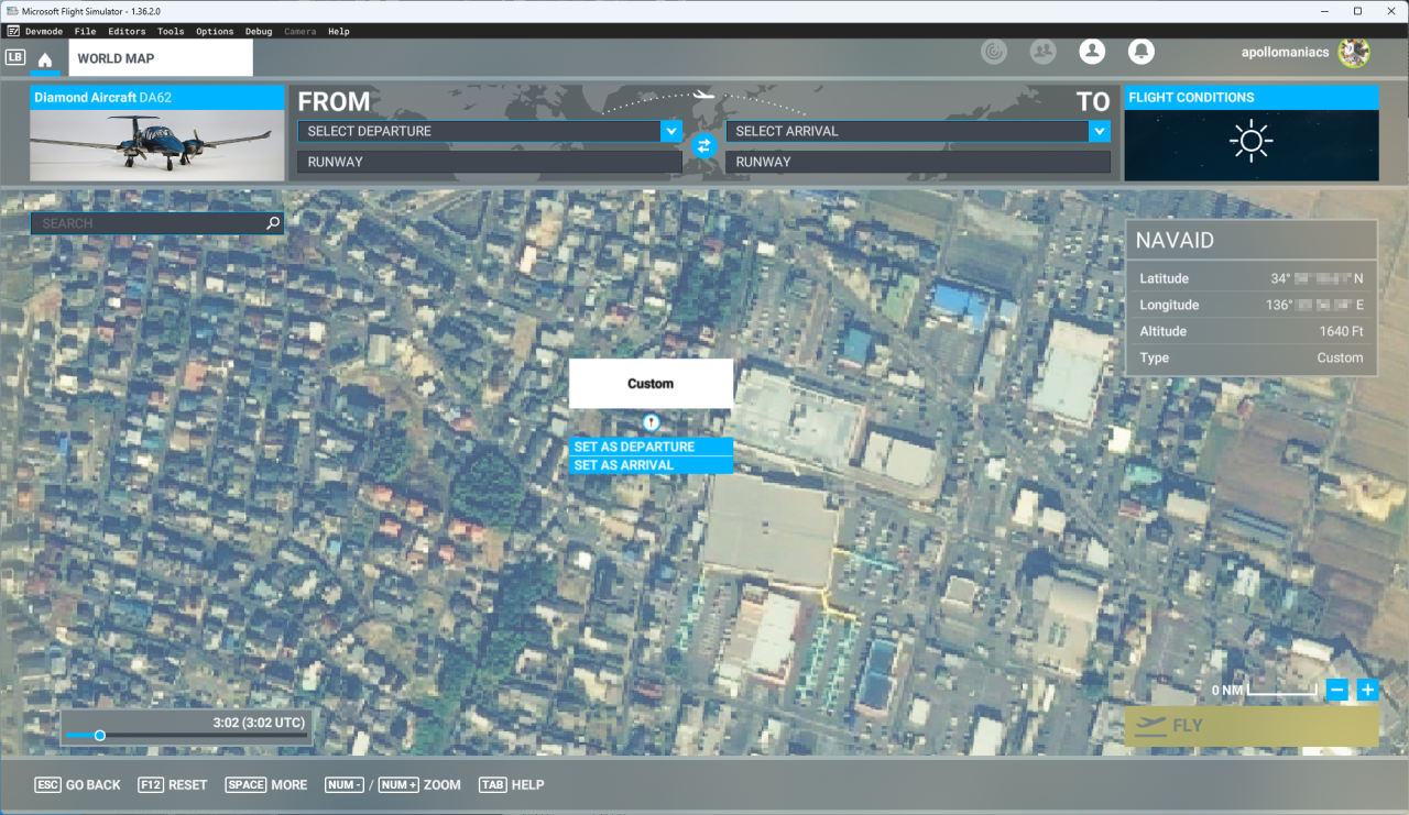
Open the WORLD MAP screen in MSFS, click on the location where you can see the scenery you created this time, and click [SET AS DEPARTURE]. Set flight conditions such as time and weather as necessary and click the [FLY] button.
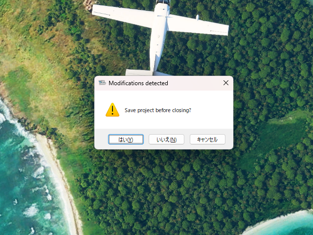 If a dialog box like this appears, the project has not been [Saved] with the MSFS SDK.
Press the [Y] key to save the project.
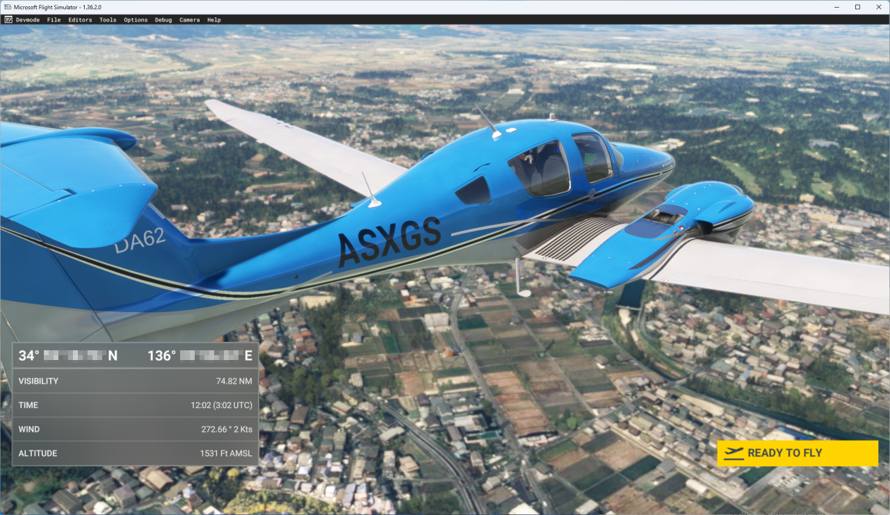
Flight begins approximately 1,500 feet above the designated location heading north.
(Flight altitude varies depending on the selected aircraft.)
If a dialog box like this appears, the project has not been [Saved] with the MSFS SDK.
Press the [Y] key to save the project.
Flight begins approximately 1,500 feet above the designated location heading north.
(Flight altitude varies depending on the selected aircraft.)
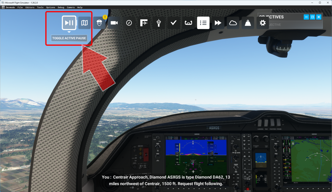 Pause immediately.
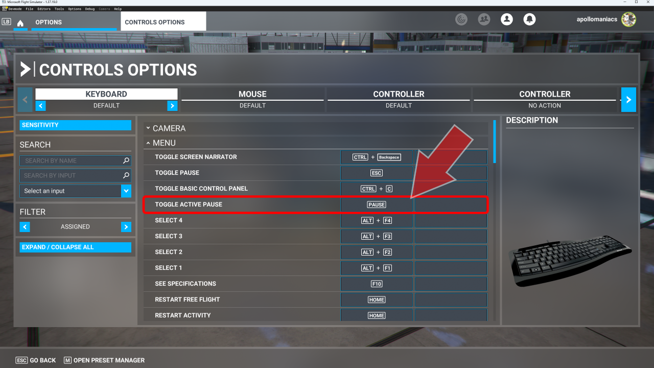 By the way, you can also turn pausing on/off during a game using the key or switch assigned to [TOGGLE ACTIVE PAUSE] in the control options.
By default it is assigned to the [PAUSE] key on your keyboard. If your keyboard has a [PAUSE] key, you can turn it on/off with that.
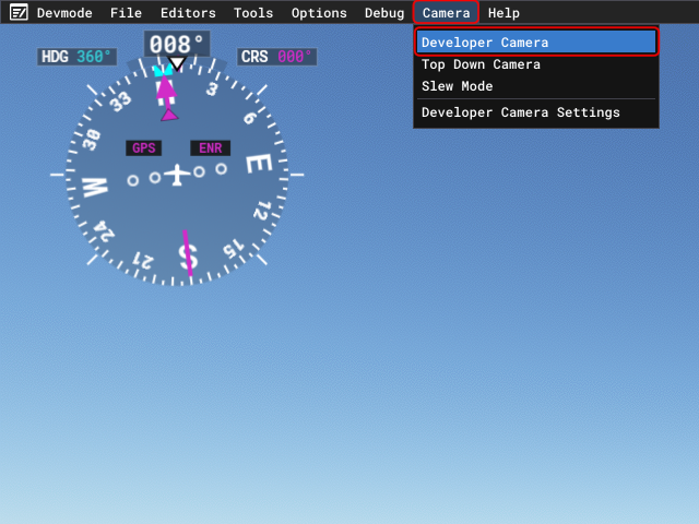 In the developer menu, select [Camera]-[Developer Camera] or [Top Down Camera].
This will change the camera (viewpoint).
Then point the camera toward the Google 3D map you generated.
You should be able to see the scenery you created.
In the developer menu, select [Camera]-[Developer Camera] or [Top Down Camera].
This will change the camera (viewpoint).
Then point the camera toward the Google 3D map you generated.
You should be able to see the scenery you created.
| Switch | Controll |
|---|---|
| left analog stick | Move the camera parallel to the front, back, left, or right |
| right analog stick | Rotate the camera up, down, left, right |
| left and right trigger | Move the camera vertically (up/down) |
| left and right buttons | Roll the camera left and right |
| Switch | Controll |
|---|---|
| left analog stick | Move the camera parallel to the front, back, left, or right |
| left and right trigger | Move the camera vertically (up/down) |
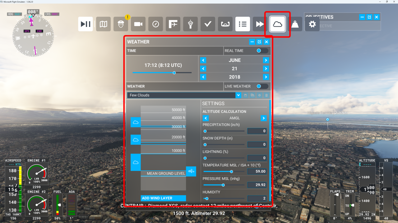 You can also change the time and weather from the toolbar.
You can check the night view.
You can also change the time and weather from the toolbar.
You can check the night view.
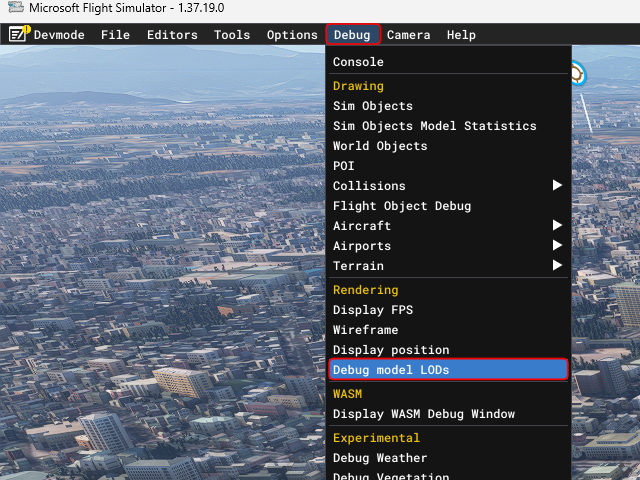 In the developer menu, select [Debug] - [Debug model LODs].
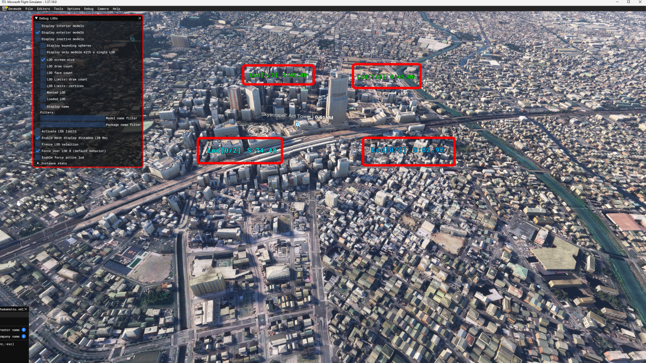 The currently displayed LOD, the number of prepared LODs (Zero Origin), and the size of the object on the screen will be displayed above each tile of the Google 3D map.
As you move the Developer Camera closer or farther away, you can see the LOD value of each tile change.
The "Debug LODs" screen also allows you to turn the display of various LOD-related information on or off.
The currently displayed LOD, the number of prepared LODs (Zero Origin), and the size of the object on the screen will be displayed above each tile of the Google 3D map.
As you move the Developer Camera closer or farther away, you can see the LOD value of each tile change.
The "Debug LODs" screen also allows you to turn the display of various LOD-related information on or off.
Many of the features you include in your package will not work on the developer mode screen. To check full functionality, you need to copy the completed package to the "Community" folder, restart MSFS, and play in normal mode.
Remove unnecessary tiles/clean up scenery
If unnecessary areas have been unintentionally imported as 3D data, you can use the MSFS SDK to delete just those tiles.
Try to delete tiles that do not contain buildings as much as possible to reduce the number of polygons.
However, even if you delete a tile with the MSFS SDK, the texture files and other associated files will remain in the project folder. You can use the Google Earth Decoder Optimization Tools (GEDOT) Blender plugin to automatically delete (clean up) such unused files.
Remove unnecessary tiles
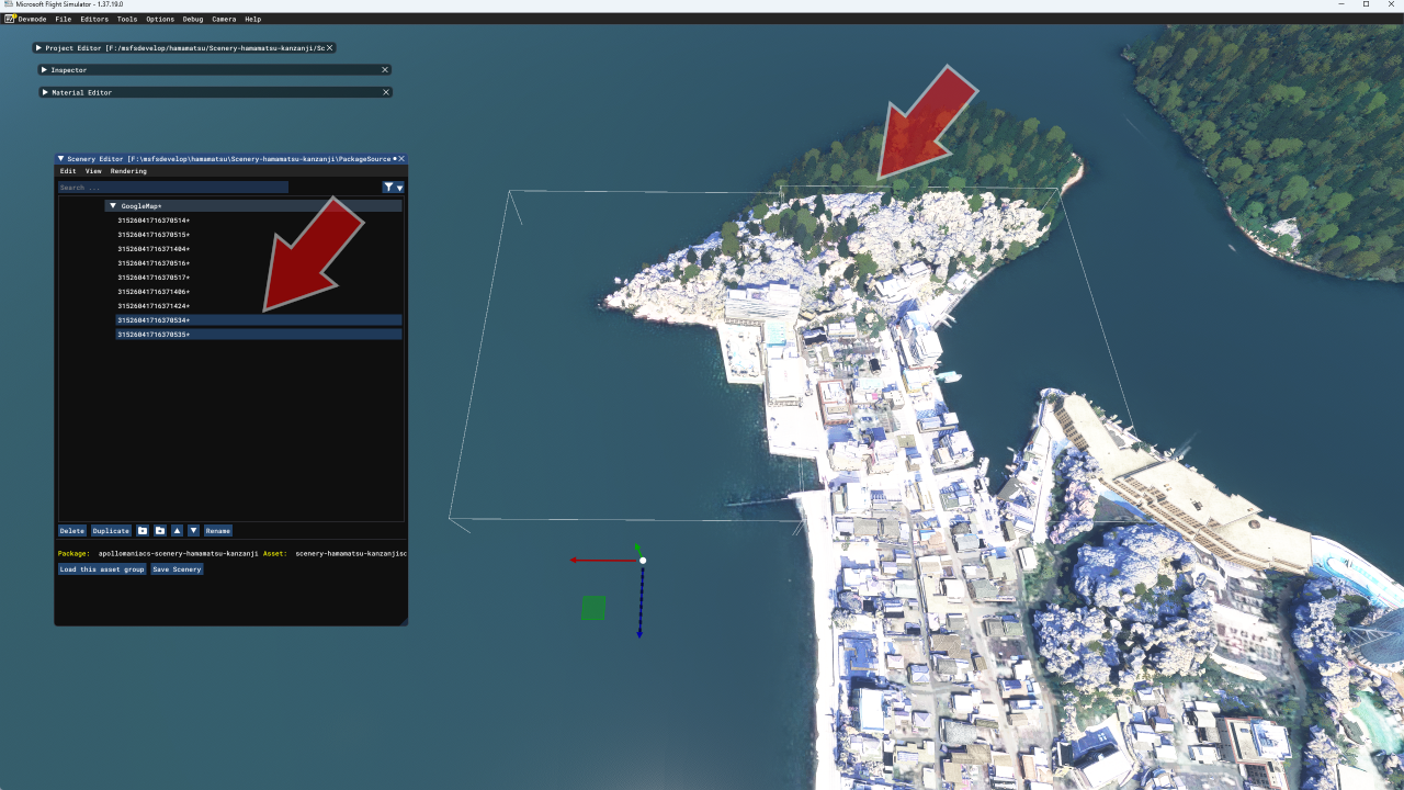 When you click a tile name on the MSFS SDK Scenery Editor screen, that tile will be surrounded by a white frame (bounding box) on the game screen.
Find the tiles you don't need.
You can select multiple tiles at the same time by holding down the [Ctrl] key and clicking the tile names.
When you click a tile name on the MSFS SDK Scenery Editor screen, that tile will be surrounded by a white frame (bounding box) on the game screen.
Find the tiles you don't need.
You can select multiple tiles at the same time by holding down the [Ctrl] key and clicking the tile names.
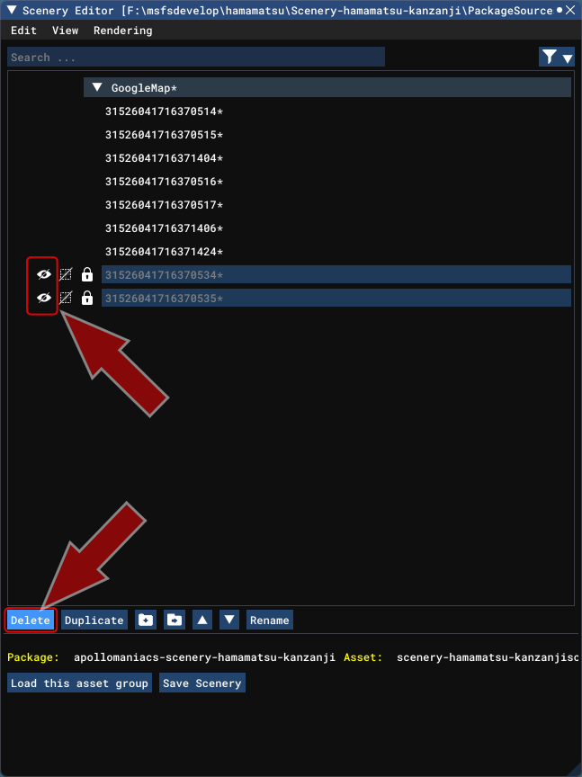 On the Scenery Editor screen, you can hide a selected tile from the game screen by clicking the eye icon to the left of the tile's name.
First, please check that you have correctly selected the tile you want to delete.
On the Scenery Editor screen, you can hide a selected tile from the game screen by clicking the eye icon to the left of the tile's name.
First, please check that you have correctly selected the tile you want to delete.
Then, click the [Delete] button at the bottom of the Scenery Editor screen to delete the selected tile.
If you delete something by mistake, select [Edit]-[Undo] from the menu on the Scenery Editor screen.
 Once you have deleted any unnecessary tiles, click the [Save Scenery] button at the bottom of the Scenery Editor screen.
Then build again.
Once you have deleted any unnecessary tiles, click the [Save Scenery] button at the bottom of the Scenery Editor screen.
Then build again.
Cleaning up the scenery
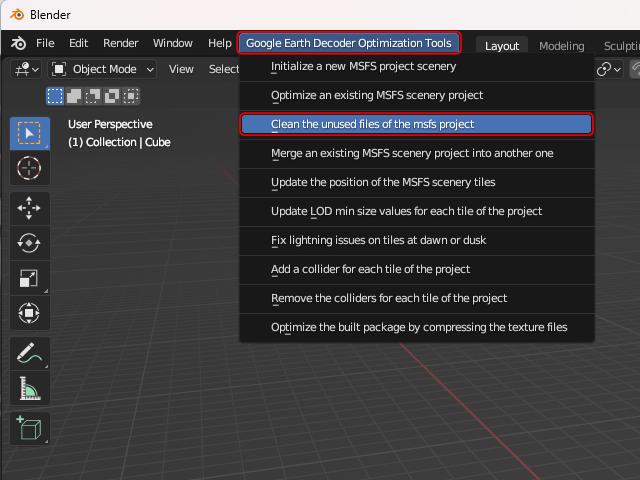 Start Blender and select [Google Earth Decoder Optimization Tools]-[Clean the unused files of the msfs project] from the menu.
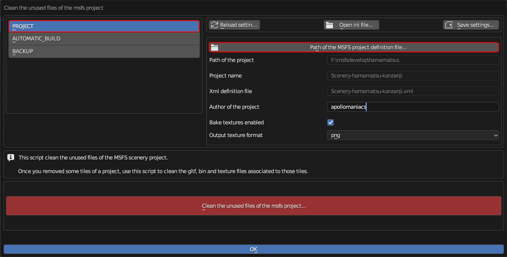 First, select [PROJECT] from the menu on the left side of the screen.
On this screen, you can specify the project you want to clean up.
Just like when
optimizing scenery data
, click on the "Path of the MSFS projects..." section in the top center of the screen,
then select "Scenery-[scenery name].xml" located directly under the project folder of the scenery to be clean up.
First, select [PROJECT] from the menu on the left side of the screen.
On this screen, you can specify the project you want to clean up.
Just like when
optimizing scenery data
, click on the "Path of the MSFS projects..." section in the top center of the screen,
then select "Scenery-[scenery name].xml" located directly under the project folder of the scenery to be clean up.
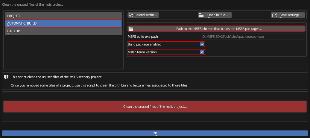 If you select [AUTOMATIC_BUILD] from the menu on the left side of the screen, you will see the screen shown on the right.
Click on the "Path of the MSFS bin exe..." in the top center of the screen to open the folder selection screen. Here, specify the location of the MSFS SDK build tool "fspackagetool.exe". This is usually located under "[MSFS SDK installation folder]\Tools\bin".
If you check Build package enabled, the build will start automatically after optimization is complete.
Also, if the MSFS you purchased is the Steam version, please check MSFS Steam version.
Finally, click the red [Clean the unused files of the MSFS project...] button to begin cleaning up your project.
Clicking the blue [OK] button will close this dialog box.
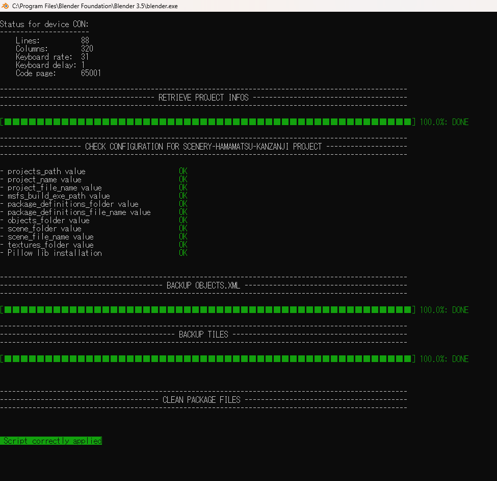 While the cleaning up is in progress, the screen will look like this.
When you see "Script correctly applied" it's complete.
While the cleaning up is in progress, the screen will look like this.
When you see "Script correctly applied" it's complete.
 If you have checked "Build package enabled", wait about 20~30 seconds and the MSFS "fspackagetool.exe" will launch and the build will begin.
When you see the message "Press any key to continue...", the build is complete.
Make sure that no errors are displayed on the screen.
Also, make sure that "0 failed" is displayed at the bottom of the screen.
If you have checked "Build package enabled", wait about 20~30 seconds and the MSFS "fspackagetool.exe" will launch and the build will begin.
When you see the message "Press any key to continue...", the build is complete.
Make sure that no errors are displayed on the screen.
Also, make sure that "0 failed" is displayed at the bottom of the screen.
If you get an error here, please refer to the How to download and install MSFS SDK, Blender, plugin, tools page to make sure you have the appropriate version of each tool.
How to download and install MSFS SDK, Blender, plugin, tools
Merging multiple scenery projects
The Google Earth Decoder Optimization Tools (GEDOT) Blender plugin allows you to merge scenery (tiles) downloaded multiple times with the Google Earth Decoder into a single project.
This is useful when you want to create a scene that is not a simple rectangle, or a scene that has outlying areas.
The tiles and textures of the scenery to be copied (source project) are copied to the main scenery (destination project). If there are overlapping tiles in both scenery, the tiles from the main scenery (destination) will be deleted. For this reason, you can first create a wide area with a low LOD value (Example: 17~19) as the main scenery, and then later merge several smaller areas created with a higher LOD value (Example: 17~21) to create a scene with high resolution models in key areas.
Note that the minimum LOD value of both scenery to be merged must be the same. Also, be careful that the contents of the PackageSources folder after merging do not exceed 7.5GB. Otherwise, an error may occur when building MSFS.
Only the tiles in the PackageSources folder and their associated information will be merged. For this reason, objects added with the MSFS SDK (such as excluded polygons and lights) will not be copied. The timing of merging can be any time as long as each scenery data has been optimized . However, after merging, you will need to build, add excluded polygons and lights, compress DDS textures, etc. again (There is an option to build automatically).
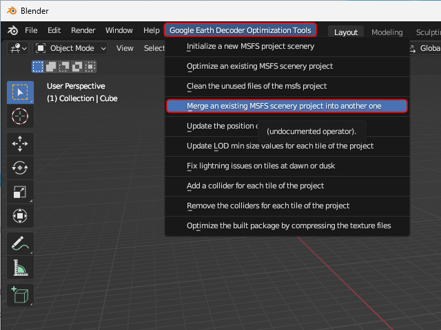 Start Blender and select [Google Earth Decoder Optimization Tools]-[Merge an existing MSFS scenery project into another one] from the menu.
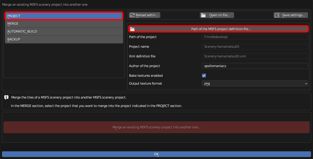 First, select [PROJECT] from the menu on the left side of the screen.
On this screen, you can specify the project that will be the main scenery (destination).
Just like when
optimizing scenery data
, click on the "Path of the MSFS projects..." section in the top center of the screen,
then select "Scenery-[scenery name].xml" located directly under the project folder of the scenery to be the main scenery (destination).
First, select [PROJECT] from the menu on the left side of the screen.
On this screen, you can specify the project that will be the main scenery (destination).
Just like when
optimizing scenery data
, click on the "Path of the MSFS projects..." section in the top center of the screen,
then select "Scenery-[scenery name].xml" located directly under the project folder of the scenery to be the main scenery (destination).
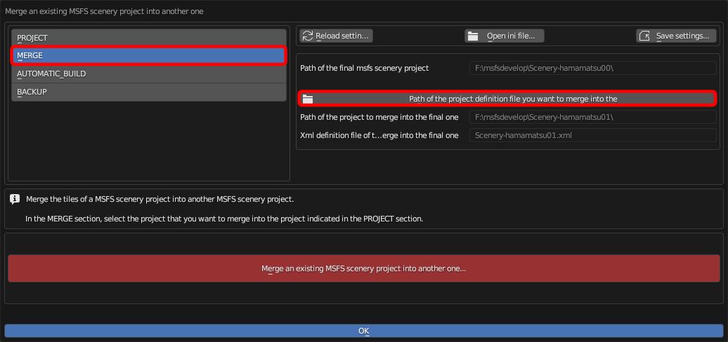 Next, select [MERGE] from the menu on the left side of the screen.
On this screen, you can specify the project that will be the scenery to be copied (source).
Click on the "Path of the project definition file..." section in the top center of the screen,
then select "Scenery-[scenery name].xml" located directly under the project folder of the scenery to be copied (source).
Next, select [MERGE] from the menu on the left side of the screen.
On this screen, you can specify the project that will be the scenery to be copied (source).
Click on the "Path of the project definition file..." section in the top center of the screen,
then select "Scenery-[scenery name].xml" located directly under the project folder of the scenery to be copied (source).
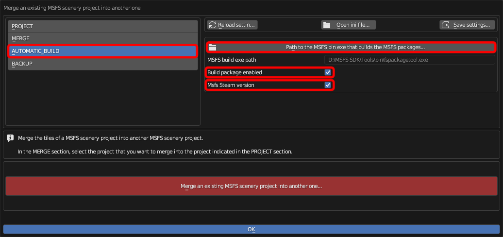 If you select [AUTOMATIC_BUILD] from the menu on the left side of the screen, you will see the screen shown on the right.
Click on the "Path of the MSFS bin exe..." in the top center of the screen to open the folder selection screen. Here, specify the location of the MSFS SDK build tool "fspackagetool.exe". This is usually located under "[MSFS SDK installation folder]\Tools\bin".
If you check Build package enabled, the build will start automatically after optimization is complete.
Also, if the MSFS you purchased is the Steam version, please check MSFS Steam version.
Finally, click the red [Merge an existing MSFS scenery...] button to begin optimizing your project.
Clicking the blue [OK] button will close this dialog box.
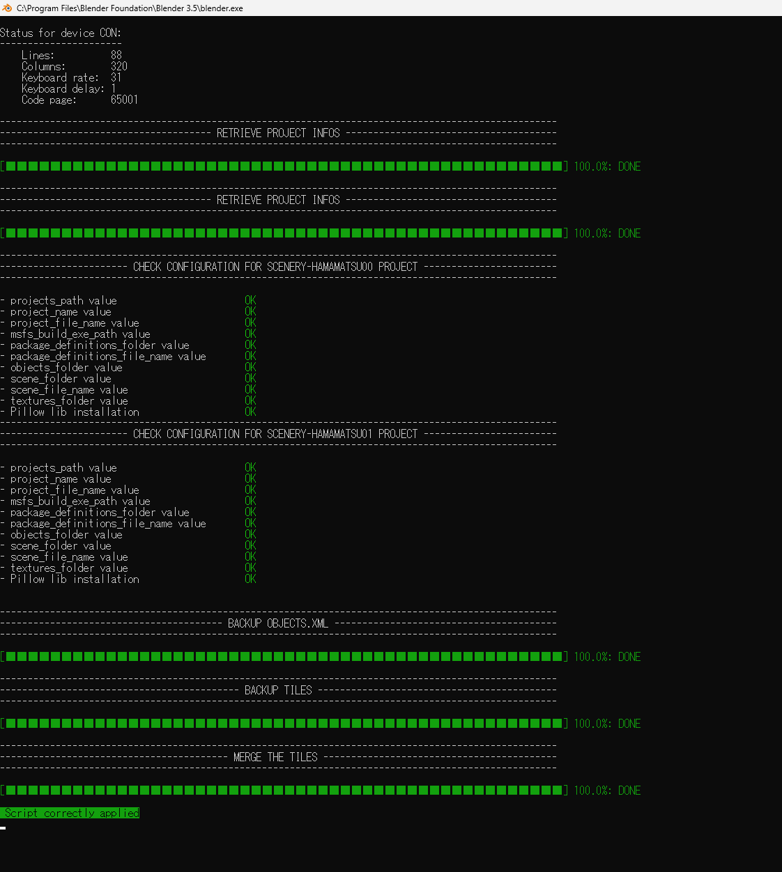 While the merge is in progress, the screen will look like this.
When you see "Script correctly applied" it's complete.
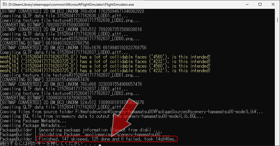
If you have checked "Build package enabled", wait about 20~30 seconds and the MSFS "fspackagetool.exe" will launch and the build will begin.
When you see the message "Press any key to continue...", the build is complete.
Make sure that no errors are displayed on the screen.
Also, make sure that "0 failed" is displayed at the bottom of the screen.
While the merge is in progress, the screen will look like this.
When you see "Script correctly applied" it's complete.
If you have checked "Build package enabled", wait about 20~30 seconds and the MSFS "fspackagetool.exe" will launch and the build will begin.
When you see the message "Press any key to continue...", the build is complete.
Make sure that no errors are displayed on the screen.
Also, make sure that "0 failed" is displayed at the bottom of the screen.
If you get an error here, please refer to the How to download and install MSFS SDK, Blender, plugin, tools page to make sure you have the appropriate version of each tool.
How to download and install MSFS SDK, Blender, plugin, tools
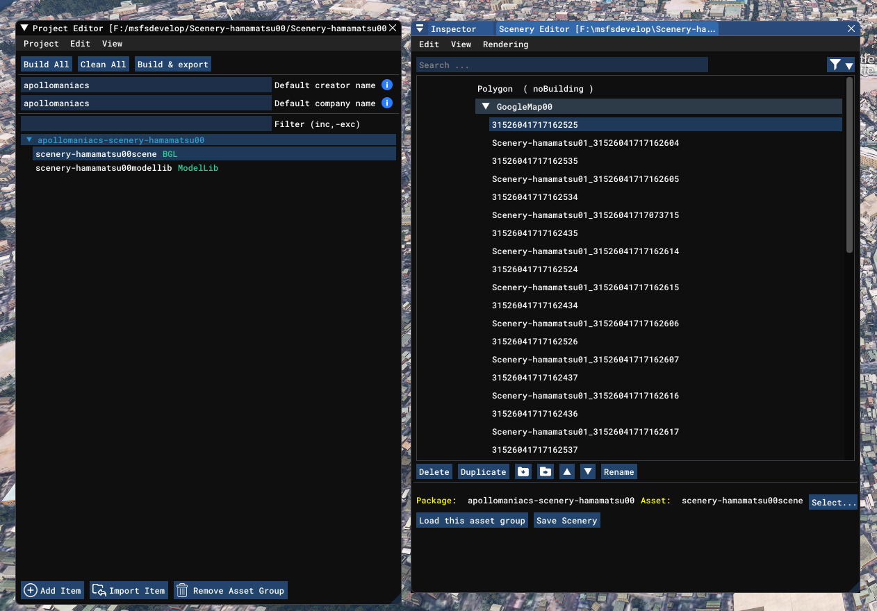 When you load the merged project into the MSFS SDK, it will look like this.
The object data names of the copied tiles have "(original package name)_" appended to them.
When you load the merged project into the MSFS SDK, it will look like this.
The object data names of the copied tiles have "(original package name)_" appended to them.
After this, add exclusion polygons as necessary.
Upgrade airport with GoogleMap/Adjust scenery altitude
Airports that do not have any buildings can be upgraded with Google Maps scenery.
You can adjust the altitude of the GoogleMap scenery to avoid interference with other objects that appear in MSFS.
 The type of package for "airports/airfields" built into MSFS is "Airport", not "Scenery".
"Airports" are not affected by the excluded polygons set in the GoogleMap scenery.
For this reason, if you place a GoogleMap scenery at a location where there is an airport, both will be displayed overlapping each other.
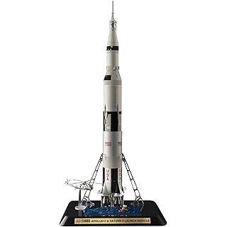
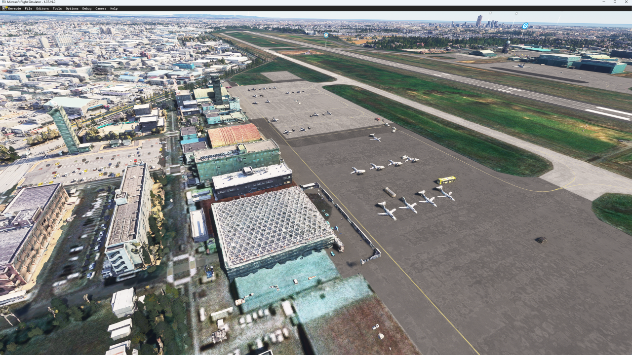
If there are no buildings built into the MSFS airport, the GoogleMap scenery buildings and aircrafts will be displayed at the airport instead (see the right image : RJNH JASDF Hamamatsu Airbase).
The type of package for "airports/airfields" built into MSFS is "Airport", not "Scenery".
"Airports" are not affected by the excluded polygons set in the GoogleMap scenery.
For this reason, if you place a GoogleMap scenery at a location where there is an airport, both will be displayed overlapping each other.
If there are no buildings built into the MSFS airport, the GoogleMap scenery buildings and aircrafts will be displayed at the airport instead (see the right image : RJNH JASDF Hamamatsu Airbase).
Usually, the altitude of an "airport" is set high, so the runway is displayed on top of the GoogleMap scenery. However, in some cases, the runway may sink below the GoogleMap scenery, or the altitude of the GoogleMap scenery may be too low, causing the building to be buried in the apron. In such cases, adjust the altitude of the GoogleMap scenery.
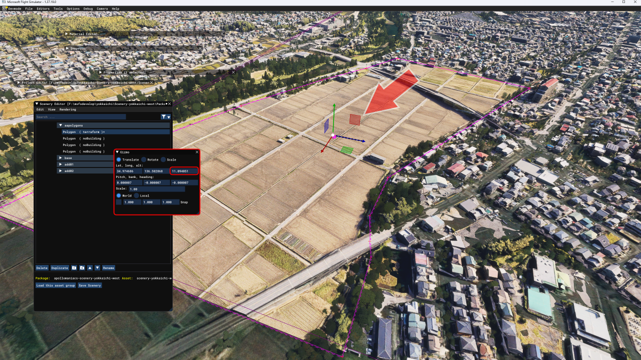
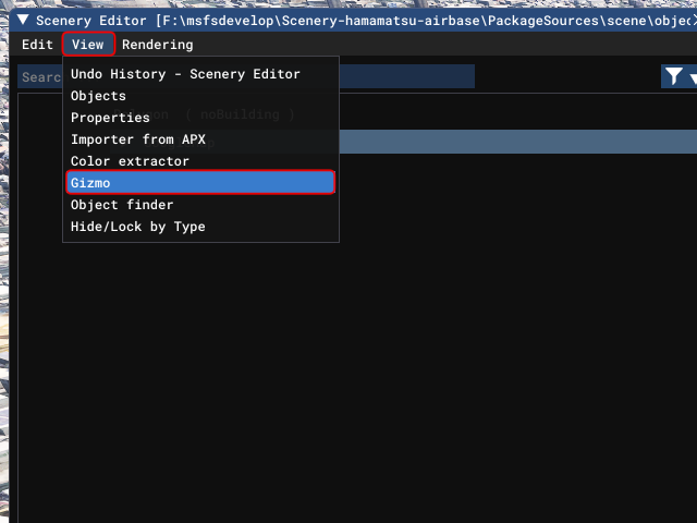 Open the Scenery Editor screen and click on the group containing the GoogleMap scenery to select it.
Then select [View]-[Gizmo] from the menu on the Scenery Editor screen.
Open the Scenery Editor screen and click on the group containing the GoogleMap scenery to select it.
Then select [View]-[Gizmo] from the menu on the Scenery Editor screen.
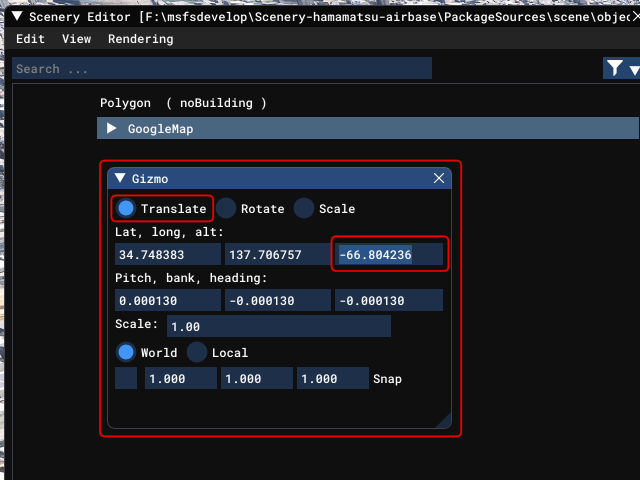 This will display the Gizmo tool screen shown on the right.
On this screen, you can move, scale, rotate, etc. the selected object.
This will display the Gizmo tool screen shown on the right.
On this screen, you can move, scale, rotate, etc. the selected object.
To adjust the altitude of an object, select "Translate" at the top, and then change the third value in the "Lat, long, alt:" field. Click on the number, enter a number from the keyboard, and press [Enter] key to update. However, it is slow to respond, so you will need some skill to update it. Try adjusting in 0.1m increments.
Once you have entered the values, click the [Save Scenery] button at the bottom of the Scenery Editor screen to save the scenery. Then build it again.
Reduce ground flickering/change MSFS ground height with terraforming polygons
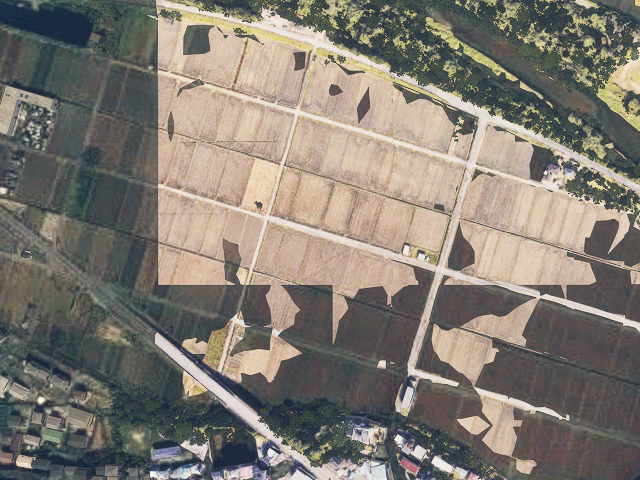 As shown in the right image, the Google scenery and the MSFS ground may be displayed mixed together, or the Google scenery ground may flicker as the camera moves.
This phenomenon occurs when the elevation of the MSFS ground is partially higher than that of the Google scenery, or when the elevations of both are very close.
As shown in the right image, the Google scenery and the MSFS ground may be displayed mixed together, or the Google scenery ground may flicker as the camera moves.
This phenomenon occurs when the elevation of the MSFS ground is partially higher than that of the Google scenery, or when the elevations of both are very close.
There are three possible ways to solve this:
- Raise the elevation of Google scenery and unify all ground to Google scenery
- Lower the elevation of Google scenery and unify everything except buildings to the MSFS ground
- Use terraforming polygons to lower (or raise) the elevation of the MSFS ground.
Here we'll introduce the third method, using terraforming polygons.
 The basic steps are the same as for
creating an exclusion polygon
:
Add a polygon object to the scenery, assign its property to Terraforming, and manipulate the elevation of that polygon.
The basic steps are the same as for
creating an exclusion polygon
:
Add a polygon object to the scenery, assign its property to Terraforming, and manipulate the elevation of that polygon.
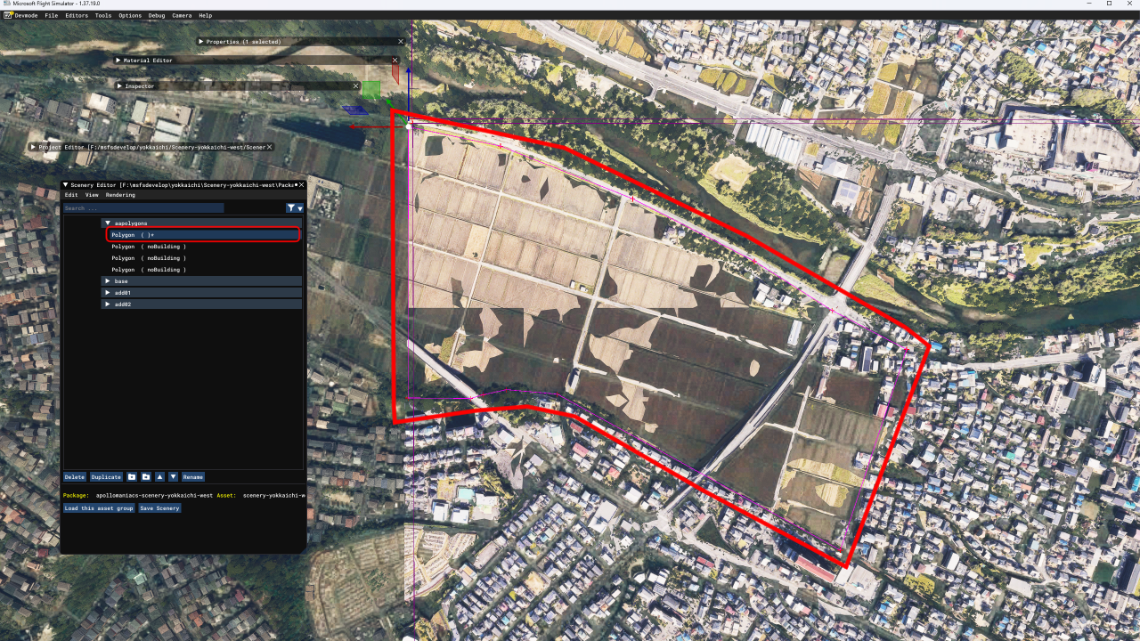
Select [View]-[Objects] from the Scenery Editor menu, select "Polygon" on the Objects screen and click the [Add] button. Then, on the game screen, hold down the [Ctrl] key and left-click the mouse to create a polygon surrounding the part of the MSFS for which you want to change the elevation.
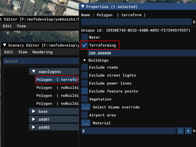 Right-click on the polygon you created in the Scenery Editor screen to open the properties screen and check "Terraforming".
This should change the way the Google scenery looks.
Right-click on the polygon you created in the Scenery Editor screen to open the properties screen and check "Terraforming".
This should change the way the Google scenery looks.
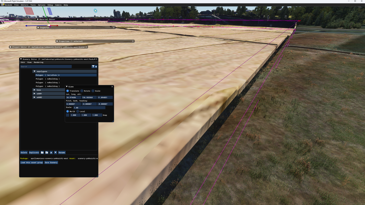
Note: When you place a terraform polygon, the MSFS ground within it will be completely flat. If you place a terraform polygon on an area that is already uneven, the MSFS ground will be partially raised or lowered. Please be aware that if you place terraforming polygons that are too large, unexpected places may rise or collapse. We recommend using it on a flat area with few irregularities from the start.
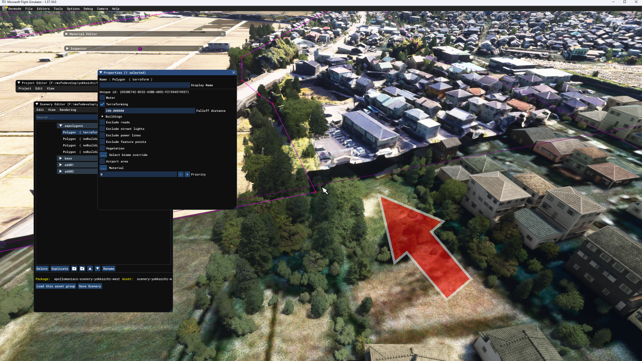 The "Falloff distance" parameter specifies how the ground deformed by the terraforming polygons connects to the original MSFS ground.
If you leave it at the default value of 200, there will be gaps between the Google scenery and the MSFS ground around the terraforming polygons, as shown in the image on the right.
The "Falloff distance" parameter specifies how the ground deformed by the terraforming polygons connects to the original MSFS ground.
If you leave it at the default value of 200, there will be gaps between the Google scenery and the MSFS ground around the terraforming polygons, as shown in the image on the right.
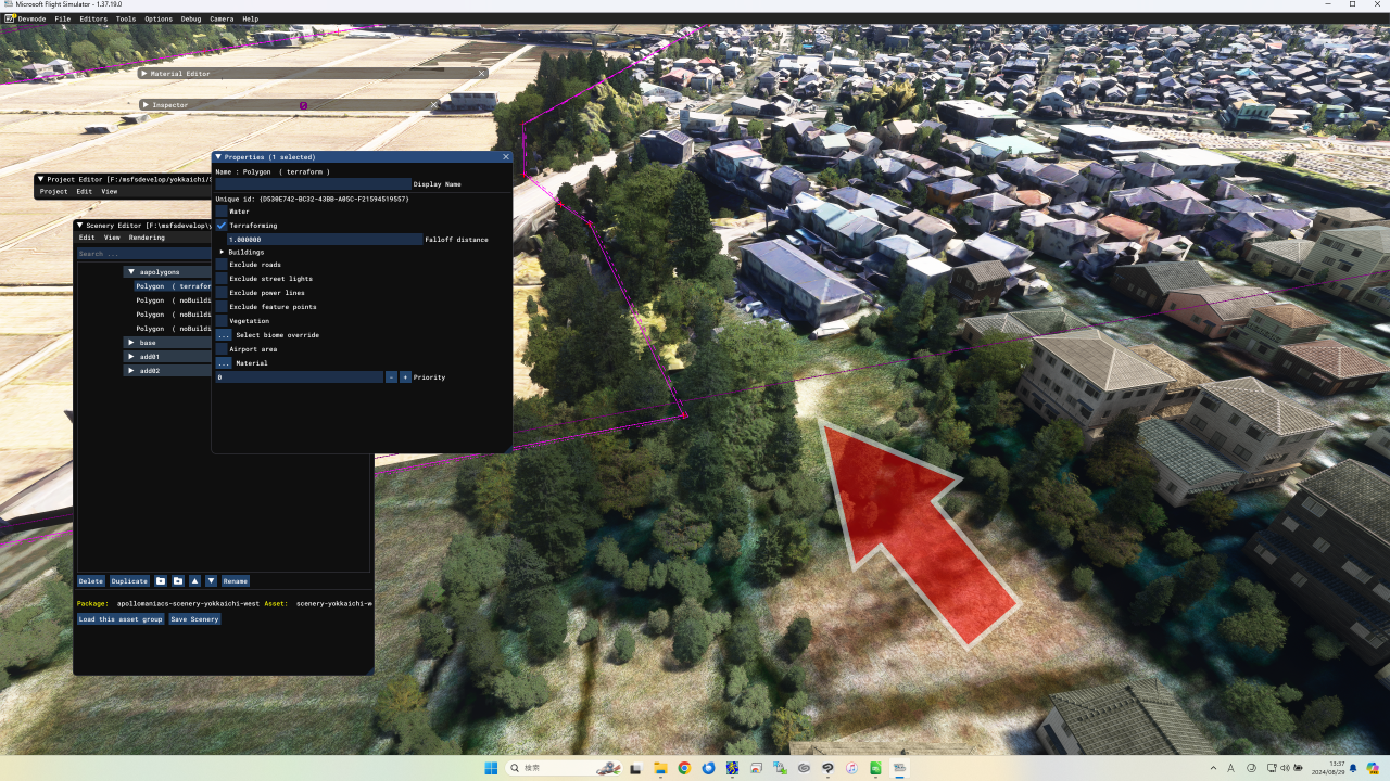 If you set the "Falloff distance" parameter to its minimum value of 1, there will be no gap as shown in the right image.
 Now let's adjust the altitude of the terraforming polygons.
Click on the terraform polygon in the Scenery Editor screen and drag the red square mark on the coordinate axis displayed on the game screen up and down to change the altitude of the terraform polygon.
Alternatively, select [View]-[Gizmo] from the Scenery Editor menu, and change the third number in the "Lat, long, alt:" column on the Gizmo tool screen.
Now let's adjust the altitude of the terraforming polygons.
Click on the terraform polygon in the Scenery Editor screen and drag the red square mark on the coordinate axis displayed on the game screen up and down to change the altitude of the terraform polygon.
Alternatively, select [View]-[Gizmo] from the Scenery Editor menu, and change the third number in the "Lat, long, alt:" column on the Gizmo tool screen.
Once you've finished making adjustments, click the [Save Scenery] button at the bottom of the Scenery Editor screen to save the scenery. Then rebuild the project.
 Even with the "Falloff distance" parameter at 1, you will see a gap between the Google scenery and the MSFS ground if you zoom in on the scenery.
To avoid this, make your terraforming polygons just a little smaller than the Google scenery.
Even with the "Falloff distance" parameter at 1, you will see a gap between the Google scenery and the MSFS ground if you zoom in on the scenery.
To avoid this, make your terraforming polygons just a little smaller than the Google scenery.
For more information about terraforming polygon parameters, see the following pages of the MSFS SDK documentation.
POLYGON OBJECTS (MSFS 2024 SDK Documentation)
POLYGON OBJECTS (MSFS SDK docs)
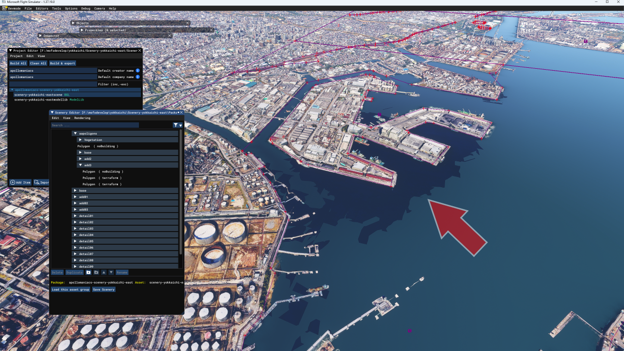 As shown in the right image, flickering may occur on the sea surface or water surface along the coastline.
This phenomenon occurs because the water surface of the Google scenery protrudes above the water surface of the MSFS.
Simply submerge the water surface of the Google scenery below the water surface of the MSFS.
As shown in the right image, flickering may occur on the sea surface or water surface along the coastline.
This phenomenon occurs because the water surface of the Google scenery protrudes above the water surface of the MSFS.
Simply submerge the water surface of the Google scenery below the water surface of the MSFS.
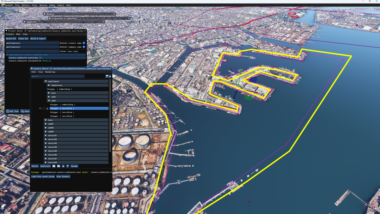 This time I solved it as follows:
I created a terraforming polygon as enclosed by the yellow line in the right image, and gradually raised the water surface of the MSFS in 0.1m increments to hide the water surface of the Google scenery. I also created a terraforming polygon that follows the coastline for the land area, and conversely pulled down the MSFS ground surface, adjusting it so that the ground surface of the Google scenery appears. The boundary between the two terraforming polygons is set so that it follows the inside of the ground surface of the Google scenery on the coastline. Otherwise, steps like waterfalls will be visible on the coastline.
Remove excess trees/Control the way trees grow with vegetation polygons
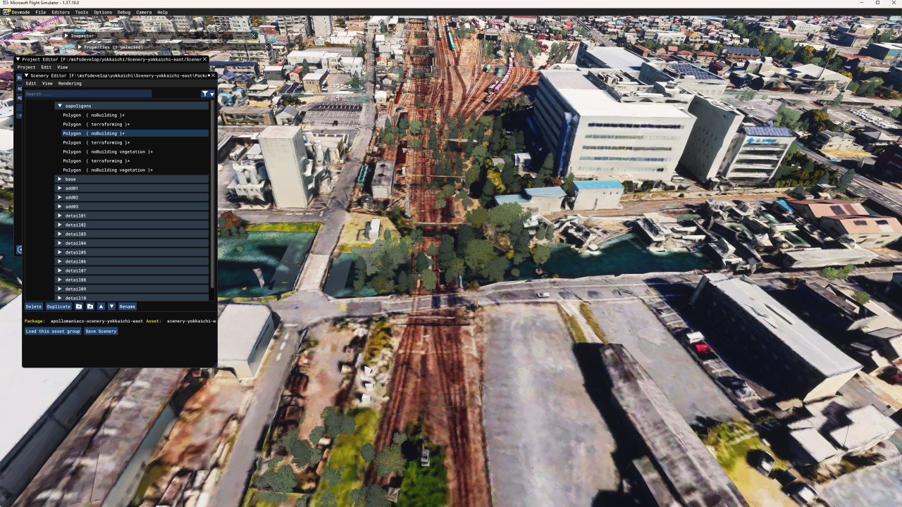 The trees and plants that MSFS automatically generates can sometimes be generated in strange places.
In the example on the right, there are trees growing over a river and railroad tracks.
The trees and plants that MSFS automatically generates can sometimes be generated in strange places.
In the example on the right, there are trees growing over a river and railroad tracks.
 By placing a "vegetation polygon" in a scenery, you can control the vegetation within it.
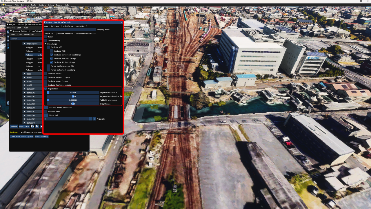
The basic steps are the same as for creating an exclusion polygon : Add a polygon object to the scenery, assign its property to Vegetation, and manipulate the parameters of that polygon.
There are four parameters, but if you set the top one, "Vegetation scale", to 0, the trees will not be visible. In a scenery created from Google Maps, it is probably a good idea to remove all trees in urban areas. Open the property screen of the exclusion polygon you have already created, check "Vegetation" too, and set "Vegetation scale" to 0.
If you want more detailed control over vegetation, place a new polygon like the Terraforming Polygon Example and manipulate the "Vegetation" parameters.
For more information about Vegetation parameters, see the following pages of the MSFS SDK documentation.
POLYGON OBJECTS (MSFS 2024 SDK Documentation)
POLYGON OBJECTS (MSFS SDK docs)
Adjust brightness and color of textures/Batch process multiple images at once
The scenery downloaded by Google Earth Decoder has too much brightness, so in the game, those parts appear whitish.
To improve this, adjust the brightness and contrast of the texture.
The adjustment amount will depend on the region of the Google Maps you downloaded and the image processing software you use, but it seems to be good to significantly lower (darken) the brightness and slightly increase the contrast.
However, there aren't many software programs that can change the brightness, saturation, and contrast of multiple bitmap files at once. As an example, we will introduce how to batch process multiple images at once using the free image processing software GIMP and its plugin BIMP.
Installing the tool
 Open the
GIMP official site
and click [DOWNLOAD] from the menu to go to the download screen.
Open the
GIMP official site
and click [DOWNLOAD] from the menu to go to the download screen.
Three buttons will then be displayed: "Download using BitTorrent," "Download directly from the official site," and "Download from Microsoft Store." Download using your preferred method.
You will be able to download a file called "gimp-2.10.38-setup.exe." Double-click this to install GIMP.
GIMP official site
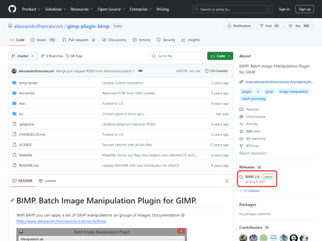 BIMP is a GIMP plug-in that allows you to adjust the image quality of multiple images at once.
Open the
BIMP official site
on github and click the [Latest] button in the bottom right of the screen.
BIMP is a GIMP plug-in that allows you to adjust the image quality of multiple images at once.
Open the
BIMP official site
on github and click the [Latest] button in the bottom right of the screen.
BIMP official site (github)
BIMP official site (alessandrofrancesconi)
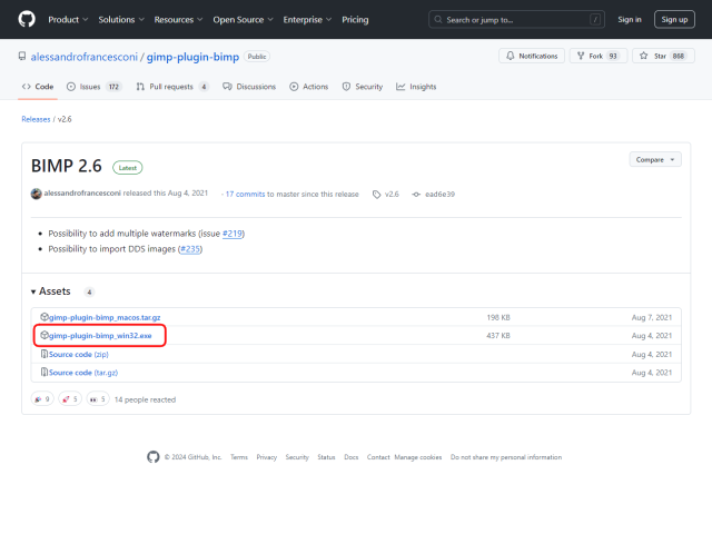 You will then see the screen on the right.
Click on "gimp-plugin-bimp_win32.exe" in the "Assets" column to download it.
Double-click this to install BIMP.
You will then see the screen on the right.
Click on "gimp-plugin-bimp_win32.exe" in the "Assets" column to download it.
Double-click this to install BIMP.
Find the brightness and color adjustment values for the texture
First, change the brightness and color of one texture of your choice and check it on the MSFS game screen.
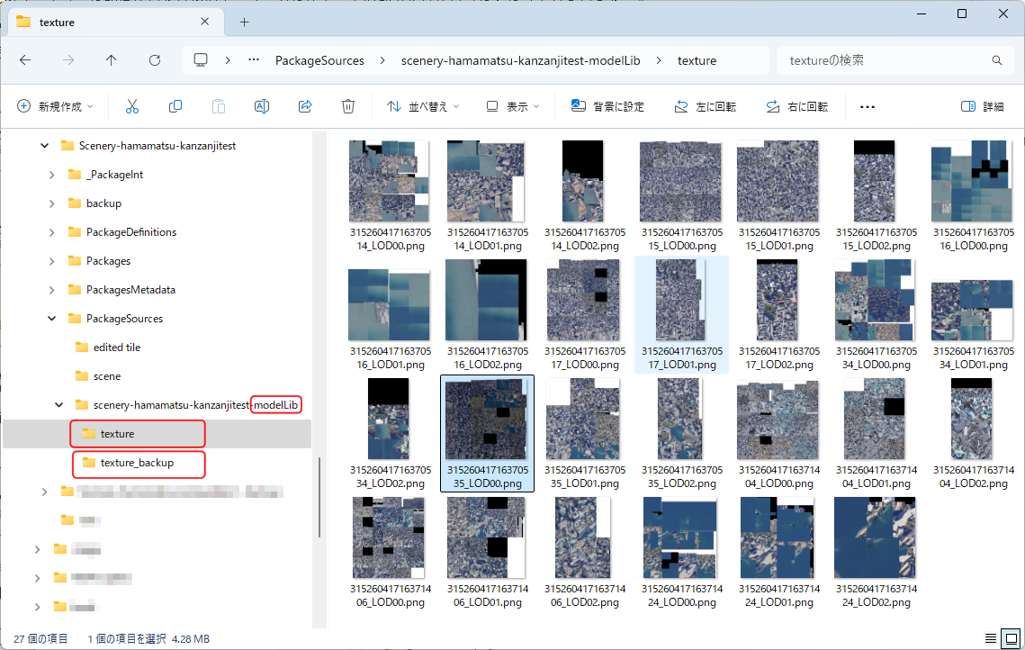 Copy the "texture" folder under the "\PackageSources\(package name)-modelLib" folder to make a backup.
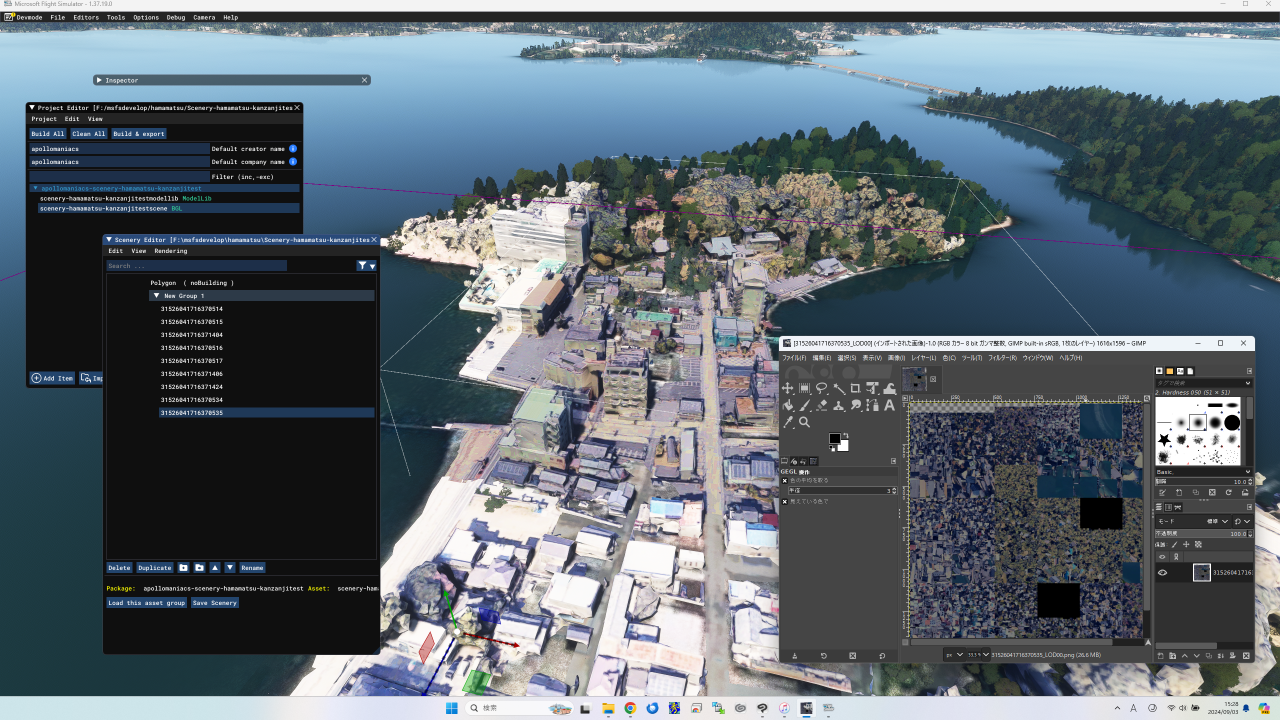 Start MSFS and click on the tile you want to adjust.
The target tile name will then be selected on the Scenery Editor screen.
Start MSFS and click on the tile you want to adjust.
The target tile name will then be selected on the Scenery Editor screen.
Next, find the corresponding texture file in the "\PackageSources\(package name)-modelLib\texture" folder.
 While MSFS is running, use image processing software (GIMP) to adjust the brightness and contrast of the corresponding texture file and overwrite it.
Clicking the [Clean All] button on the Project Editor screen will delete old packages under the "Packages" folder.
Next, click the [Build All] button to start the build.
Once the build is complete, the texture modifications will be reflected on the game screen.
While MSFS is running, use image processing software (GIMP) to adjust the brightness and contrast of the corresponding texture file and overwrite it.
Clicking the [Clean All] button on the Project Editor screen will delete old packages under the "Packages" folder.
Next, click the [Build All] button to start the build.
Once the build is complete, the texture modifications will be reflected on the game screen.
Repeat adjusting the texture, building the project, and checking the game screen to find the appropriate adjustment values.
Once you have determined the adjustment values, note them down and restore the texture file from your backup.
Batch process multiple images at once
Once the texture adjustment values have been decided, batch convert all the textures that make up the scenery.
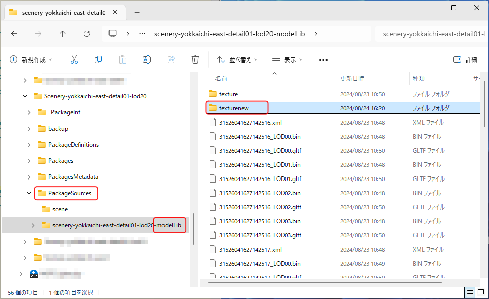 First, create an output folder to save the processed image files.
In this example, we created a folder named "texturenew" under the
"\PackageSources\(package name)-modelLib\"
folder of the input target project.
First, create an output folder to save the processed image files.
In this example, we created a folder named "texturenew" under the
"\PackageSources\(package name)-modelLib\"
folder of the input target project.
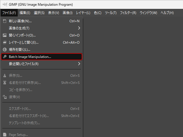 Start GIMP.
Then select [File]-[Batch Image Manipulation] from the menu.
Start GIMP.
Then select [File]-[Batch Image Manipulation] from the menu.
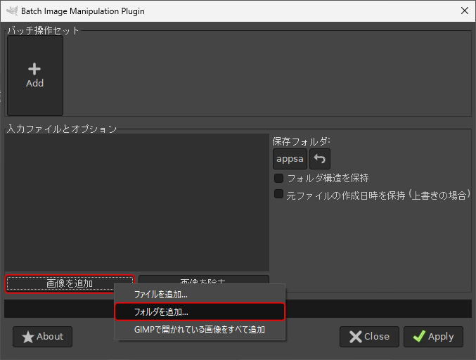 This will open a dialog window like this.
First, select an input folder.
Click the [Add Images] button at the bottom left of the screen, then click [Add Folder].
You will then be taken to the folder selection screen.
This will open a dialog window like this.
First, select an input folder.
Click the [Add Images] button at the bottom left of the screen, then click [Add Folder].
You will then be taken to the folder selection screen.
Select the "\PackageSources\(package name)-modelLib\texture" folder of the target project.
Then click the “+Add” button at the bottom right of the folder selection screen.
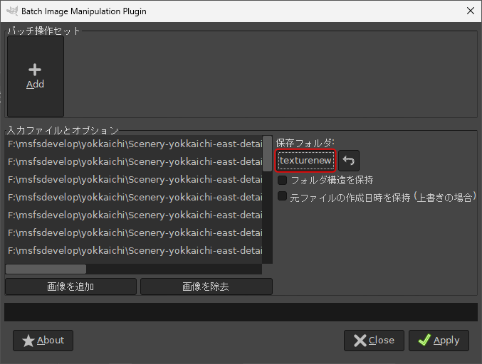 Click on the text box below that says "Save Folder:".
You will then be taken to the folder selection screen.
Select the output folder you created earlier.
Click on the text box below that says "Save Folder:".
You will then be taken to the folder selection screen.
Select the output folder you created earlier.
Then click the “Ok” button at the bottom right of the folder selection screen.
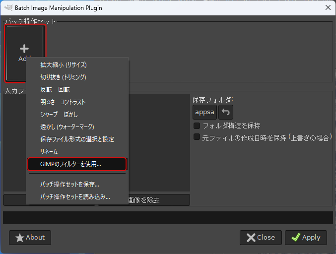 Clicking the [Add] button at the top left of the screen allows you to specify the processing to be performed on the image file.
To manipulate hue, saturation, and lightness, select [Use GIMP Filter].
Clicking the [Add] button at the top left of the screen allows you to specify the processing to be performed on the image file.
To manipulate hue, saturation, and lightness, select [Use GIMP Filter].
 You will then see the screen on the right.
When you select a filter on the left side of the screen, the settings screen will appear on the right.
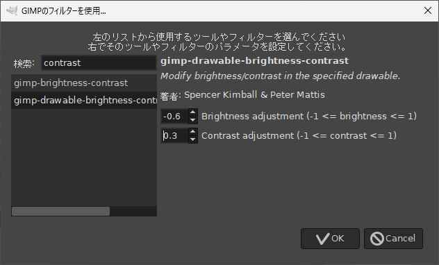
If you enter "contrast" in the search box on the left side of the screen, the names of two filters that handle contrast will be displayed.
Select [gimp-drawable-brightness-contrast].
You will then see the screen on the right.
When you select a filter on the left side of the screen, the settings screen will appear on the right.
If you enter "contrast" in the search box on the left side of the screen, the names of two filters that handle contrast will be displayed.
Select [gimp-drawable-brightness-contrast].
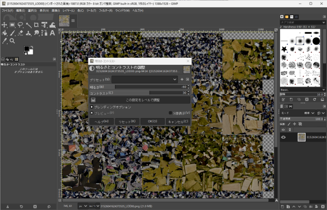
Then, on the right side of the screen, set the brightness and contrast adjustment values. For the scenery I created this time, I set "Brightness" to "-0.6" and "Contrast" to "0.3" which looked good.
Then click the "Ok" button at the bottom right of the screen.
The only way to determine the value you specify here is through trial and error. Try converting and checking in the game screen repeatedly to find the appropriate value for the scenery you have downloaded.
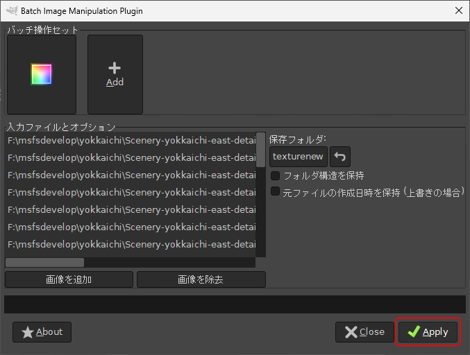 Finally, click the [Apply] button at the bottom right of the screen to start the conversion.
The time it takes to convert varies depending on the size of the scenery and the number of LODs, but it takes about an hour for a scenery of several square kilometers.
Finally, click the [Apply] button at the bottom right of the screen to start the conversion.
The time it takes to convert varies depending on the size of the scenery and the number of LODs, but it takes about an hour for a scenery of several square kilometers.
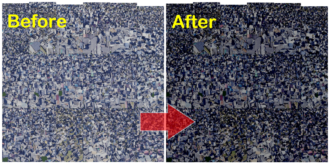 Here's a comparison of the texture before and after conversion.
The converted texture is a very dark image, but it will have just the right brightness on the game screen.
Rename the input folder "texture" to, for example, "textureold", and rename the output folder "texturenew" to "texture".
Here's a comparison of the texture before and after conversion.
The converted texture is a very dark image, but it will have just the right brightness on the game screen.
Rename the input folder "texture" to, for example, "textureold", and rename the output folder "texturenew" to "texture".
Next, start MSFS, load the project into the game screen , and build it with the MSFS SDK to complete the project. Click the [Clean All] button on the Project Editor screen to delete old packages. Then click the [Build All] button to start the build.
Please note that if you do not click the [Clean All] button, the texture changes will not be reflected.
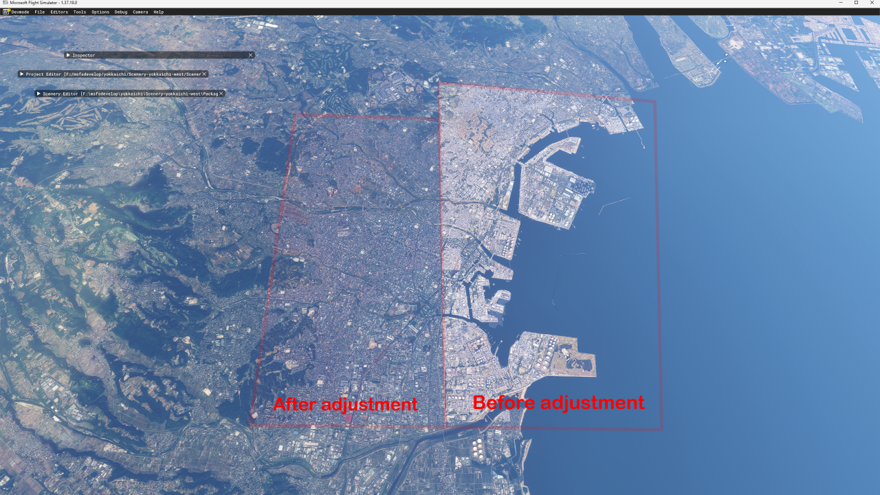 We compared the scenery before and after conversion on the game screen.
The red frame on the left is the scenery after brightness and contrast adjustments, and the red frame on the right is the scenery without adjustments.
You can see that with this processing, the scenery blends in with the surrounding scenery.
We compared the scenery before and after conversion on the game screen.
The red frame on the left is the scenery after brightness and contrast adjustments, and the red frame on the right is the scenery without adjustments.
You can see that with this processing, the scenery blends in with the surrounding scenery.
Once you have successfully adjusted the textures as expected, you can delete the initial texture backup and the "textureold" folder.