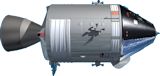


Service Module(SM)
The Service Module supplies the electrical power, water, oxygen, and life support necessary for the CM and astronauts for the trip from the Earth to the Moon.
The SM also controls the flight path of the CSM/LM stack.
The SPS engine of the SM provides the thrust necessary to leave Earth orbit to begin translunar coast, and then to leave lunar orbit and return to Earth.
 from -Z View")
 from -Y View")
 from +Z View")
 from +Y View")
 from -X View")
 from +X View")
- Height : 24ft 5in (7.4422m)
- Body:14ft 8in (4.4704m)
- SPS nozzle :9ft 9in (2.9718m)
- Diameter : 12ft 10in (3.9116m)
- Maximum Weight : 55000lb (24.97ton)
- Manufacturer : North American Rockwell Corp. Space Div., Downey, Calif.
Structure
")

The SM body is made of aluminum honeycomb core between two aluminum face sheets, with a thickness of about one inch. The "spine" of the SM is made of a 44-inch (1.11m) diameter cylinder installed in the center of the SM, with 6 sections (Sector 1 to Sector 6) surrounding it. The 360 degrees around this center section is divided among two 50-degree sections (Sectors 1 and 4), two 60-degree sections (Sectors 3 and 6), and two 70-degree sections (Sectors 2 and 5).
Center Section
Two 40-inch diameter globular helium tanks and the SPS engine are located here. Each helium tank carries 19.6 cubic feet of helium gas, pressurized at 3600psi. These are used to "pump" fuel and oxygen for the SPS engine. The fuel is "pumped" to the engine from the tanks by injecting this inert gas.
 Sector 1: SIM(Scientific Instrumentation Module) Bay")
Sector 1
A weight to help balance the SM was carried in this sector from Apollo 1 through Apollo 14. For Apollo 15 through 17, this was used as the SIM (Scientific Instrumentation Module) Bay. A high-resolution camera as well as radiation measurement devices were carried here to probe the surface of the moon from lunar orbit.

Sector 2
An RCS engine quad and a radiator panel are installed on the outside panel of this sector. An oxidizer sump tank for the SPS engine, and an RCS fuel tank and conduits are installed inside. The oxidizer sump tank can hold 13923lb of nitrogen tetroxide, and is manufactured of titanium, with a height 153.8 inches, and a diameter of 51 inches.
Sector 3
An RCS engine quad and a radiator panel are installed on the outside panel of this sector. An oxidizer tank for the SPS engine, and an RCS fuel tank and conduits are installed inside. The oxidizer tank is a little smaller than the oxidizer sump tank, and carries 11284lb of oxidizer, with a height 154.47 inches, and a diameter of 45 inches.
Sector 4
 Sector 4 : fuel cell, oxygen tanks, hydrogen tanks")
The center of this sector contains the two cryogenic oxygen tanks, and the two cryogenic hydrogen tanks, arranged with the oxygen tanks at the top, and the hydrogen tanks at the bottom. All of these tanks are spherical and supply oxygen and hydrogen to the fuel cell power plants.

The cryogenic hydrogen tank is made of about 31.75-inch diameter titanium. It carries a little over 29lb of super-cooled hydrogen, in a semi-liquid, semi-gas state.
The Apollo 13 emergency was due to the explosion of the Number 2 cryogenic oxygen tank carried here. Therefore, one spare cryogenic oxygen tank in Sector 1, and one spare battery in Sector 4 were added after Apollo 13.
 Ed Hengeveld")
Sector 5
An RCS engine quad and an environmental control radiator panel are installed on the outside panel of this sector. A fuel sump tank for the SPS engine, and an RCS fuel tank and conduits are installed inside. The fuel sump tank can hold 8708lb of propellant (a 50-50 mixture of hydrazine and unsymmetrical dimethylhydrazine), and is manufactured of titanium with a height of 153.8 inches, and a diameter of 51 inches.
Sector 6
An RCS engine quad and an environmental control radiator panel are installed on the outside panel of this sector. A fuel storage tank for the SPS engine, and an RCS fuel tank and conduits are installed inside. The size of the fuel storage tank is same as the oxidizer tank in Sector 3, and carries 7058lb of propellant, and has a height of 154.47 inches, and a diameter of 45 inches.
Antenna
 high-gain S band antenna")

 scimitar antenna")
RCS engine
 RCS(reaction control subsystem) engine")
 RCS diagram")
SPS engine


A heat shield in installed on the end of the SM where the SPS engine bell is attached, protecting the SM from the heat of the SPS engine.
Connection, separation with CM
 top detail")
The separation of the SM and CM is done automatically by a controller installed in the SM. Cutting of the connectors, the transfer of the control of the electric system and jetting of the SM RCS engine to draw CM and SM apart are done almost instantaneously at the time of the separation.
First, before the separation, astronauts pressurize the CM RCS by using electrical power provided by the SM. The separation sequence begins when either one of two switches on the main console is toggled. The electrical transfer through the CM-SM umbilical is disabled first. After 10 seconds, the tension ties that connect the SM with the CM are separated. At the same time, the stainless steel guillotine cutter is fired by explosives, cutting the cables and wires in the CM-SM umbilical. Finally, the RCS engines of the SM fire for five seconds, the flight course of SM is changed to avoid a collision with the CM. Until the fuel is used up or electric power is expended, the SM RCS keeps firing to ensure that the SM's flight path stays away from the CM.
CSM color chart
 SPS engine")
 SPS engine plumbing")
 forward fairing contents")
 Sector 1: SIM(Scientific Instrumentation Module) Bay")


")
")
Thanks to Jonathan Long for revice my poor English.