Mobile Launcher & Launch Umbilical Tower for Apollo Program
Mobile Launcher(ML)

This is a mobile launch platform. Saturn V booster was assembled on this ML and transported by Crawler Transporter(CT) to Launch Pad . And rockets fly up from this on to the moon.

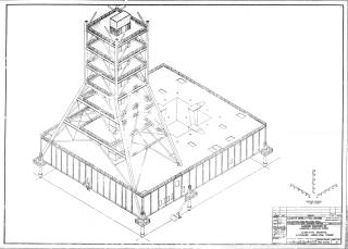
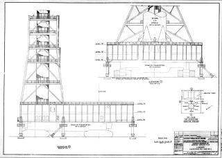
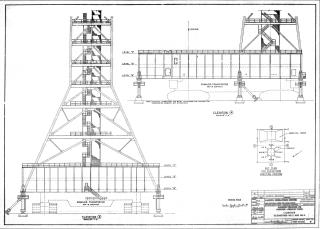
The height is 445 ft (about 135.6 m) from the ground, 490 ft 6 inches (about 149.5 m) to the tip of the lightning rod, and the weight is 10.5 million pounds (about 4,763 tons). ML consists of two-story pedestal (Launcher Base) painted in gray, amber LUT(Launch Umbilical Tower) with a hammerhead crane at the top, and 10 Support legs with a height of 22 ft (approximately 6.7 m).
From July 1963 to March 1965, a total of three MLs, from ML-1 to ML-3, were manufactured and constantly remodeled according to the missions used thereafter. There are total of 17 launch missions for the Apollo program, where ML was used, first mission was Apollo 4 (SA-501), the first Saturn V rocket unmanned test flight launched in May 1966, and the last was Apollo Soyuz Test Program (ASTP: SA-210), launched in March 1975.
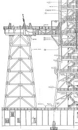
Launch Umbilical Tower(LUT)

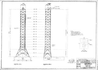
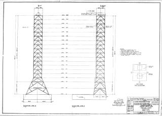
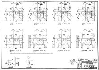
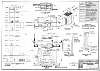
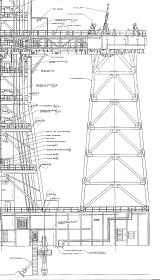
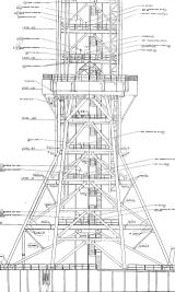
This is "international orange" painted iron structure mounted on the Launcher Base to provide fuel, pneumatic, electricity, water, communications etc to vehicle. The height is 380 ft (about 115.8 m) from Launcher Base, and it is 18 floors in total. The first and second floors have a height of 30 ft (about 9.1 m), the others each have a height of 20 ft (about 6.1 m), and each floor is called the height (ft) from the top of the Launcher Base. For example, the second floor is "Level 30", the third floor is "Level 60", and the top 18th floor is called "Level 360". A hammerhead crane, which can rotate 360 degrees and lift a weight of 10 to 25 tons, is installed on the roof at Level 380. Two high-speed elevators, which go up and down at 600 ft (183 m) per minute, connect floor A of the Launcher Base to Level 340 of the LUT.


In an emergency such as a fire, astronauts and engineers take two high-speed elevators to evacuate LUT work floor. After getting off the elevator, take a metal chute (Escape tube) from Levle A to avoid blast, and retreat to a heat-resistant room (Blast room) provided inside the hard stand of the pad. Blast room has a sturdy metal door like a bank safe and can withstand explosion of the entire rocket. The people inside can stay alive for at least 24 hours until the rescue team digs out and rescues them. Alternatively, take the elevator B down to below Pad and get on the armored vehicle and leave Pad.
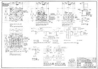
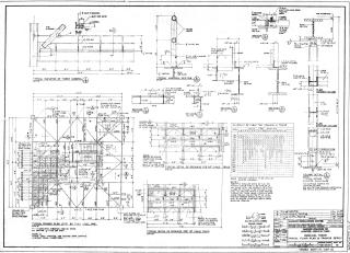
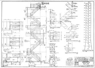
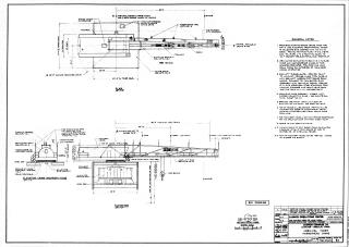
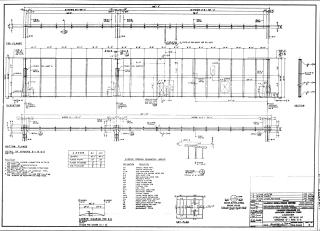
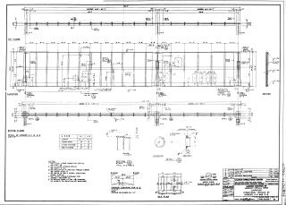
Drawings
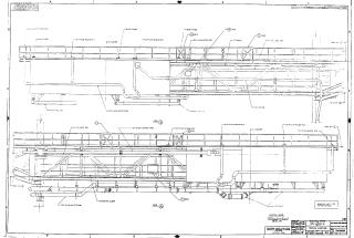
Service arms and Access arm


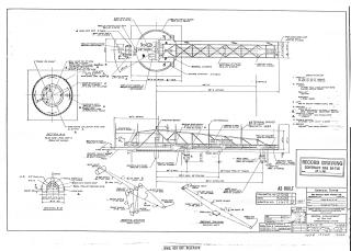
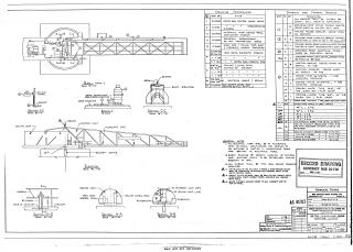
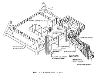
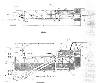
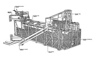
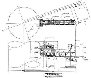
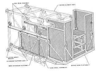
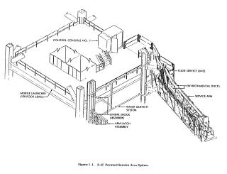
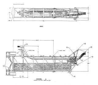
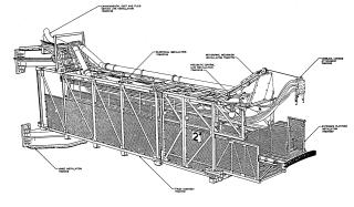
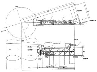
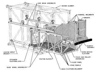
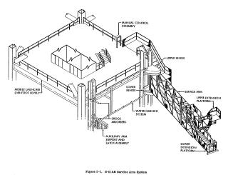
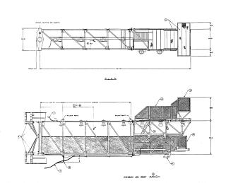
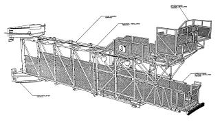
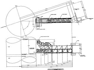
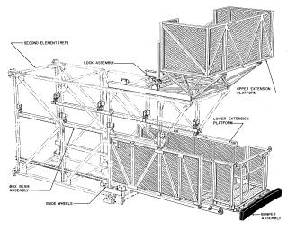
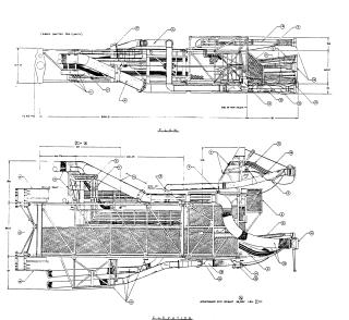
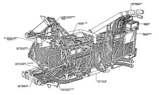
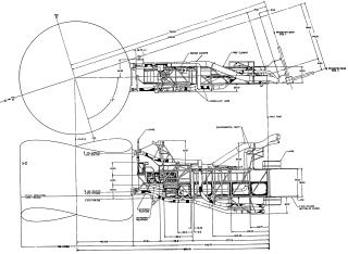
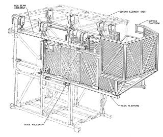
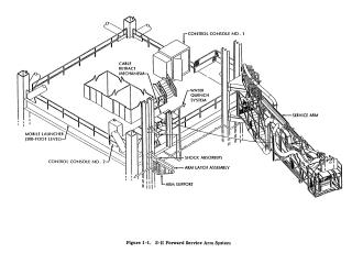
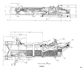
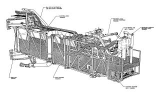
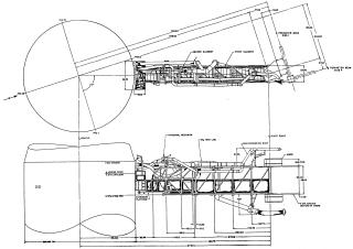
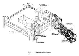
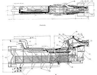
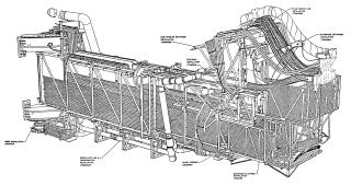
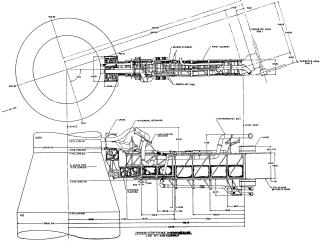
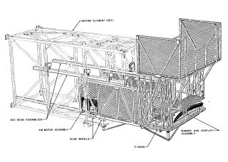
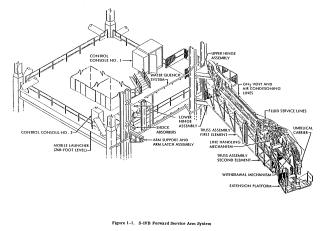
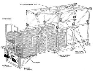
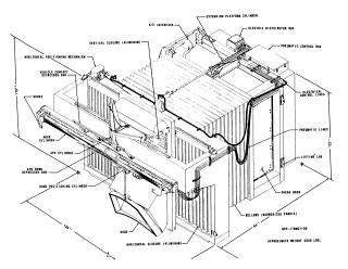
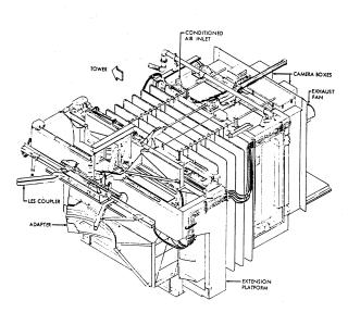
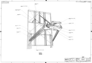
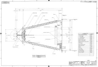
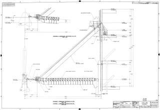
A total of nine arms, eight service arms and one access arm, are attached to LUT. These are also called swing arms. Each arm is sized to allow maintenance personnel to pass through the expansion platform to access the booster inspection hatch (some were wide enough for a jeep to drive across). The average weight of each arm is over 22 tons.
During the assembly and checkout of the Saturn V, full functional testing of all service arms and Tail Service Masts connected to the lower end of the S-IC was performed. The umbilical housing at the tip of each arm was tested for detachment from the rocket, retraction of the folding function, rotation of the arm, etc.

The arms are classified into two types, preflight and inflight, according to the folding method at launch. The preflight-type arms are detached from the vehicle at T-10 seconds (10 seconds before launch) and locked to the tower. The inflight-type arms are disconnected during takeoff by the lift-off switch which installed in the Hold-Down Arms, triggered by the launch of the rocket's vertical ascent. All were operated with pneumatics and hydraulics, and are equipped with spare systems in case of failure.
Arm No.1 : S-IC Intertank (preflight)

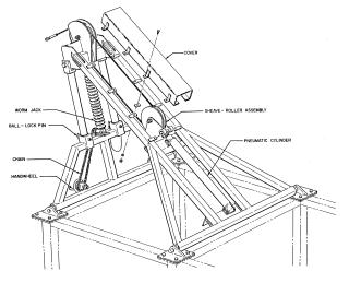
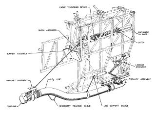
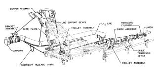
Provides two interfaces for the supply and exhaust of LOX (Liquid Oxygen) used as an oxidant. The umbilical connector is retracted by composite parallel links driven by pneumatics. After being separated, the arm is rotated and folded by hydraulic pressure. This arm can be remotely reconnected from the LCC to eject the LOX from the S-IC if launch is discontinued. If the launch is canceled after T-10 seconds, it was reconnect with the command from LCC. It takes 8 seconds to disconnect the arm, and takes about 5 minutes to reconnect.
Arm No.2 : S-IC Forward (preflight)

Provides 7 pneumatics, 8 electricals, 1 liquid nitrogen, and 2 air conditioning interfaces. The umbilical connector is pulled in, rotated and folded by the pneumatics itself and a block driven by pneumatics, and a combination of a pulley and a lanyard. Furthermore, a mechanical system assists. This arm is disconnected at T-19 seconds. It takes 8 seconds to disconnect the arm.
Arm No.3 : S-II Aft (preflight)

This is used by engineers to access the vehicle inside. It also provides a single LOX pump exhaust line interface. This arm is retracted early before launch, as needed.
Arm No.4 : S-II Intermediate (inflight)

Provides LH2 (liquid hydrogen) and LOX injection / exhaust lines used as fuel, pneumatics, equipment cooling, electrical, air conditioning interface. Retraction of the umbilical connector is the same system as the arm 7 (S-IVB Forward). A lanyard system driven by a pneumatic cylinder is added in case of a retraction system failure. It takes up to 6.4 seconds to disconnect the arm.
Arm No.5 : S-II Forward (inflight)

Provides 2 GH2 (gaseous hydrogen) exhausts, 1 instrument cooling, 8 electricals, 6 pneumatics, 1 air conditioning interface. Retraction of the umbilical connector is the same system as the arm 7 (S-IVB Forward). It takes up to 7.4 seconds to disconnect the arm.
Arm No.6 : S-IVB Aft (inflight)

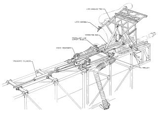
Provides 1 LH2 injection, 1 LOX injection, 6 electricals, 11 pneumatics and equipment cooling, 1 air conditioning interface. Retraction of the umbilical connector is the same system as the arm 7 (S-IVB Forward). It also has a line handling device that protects the cables during the pull-in operation. It takes up to 7.7 seconds to disconnect the arm.
Arm No.7 : S-IVB Forward and Instrument Unit (inflight)

Provides exhaust for one hydrogen tank, 24 electricals, one pneumatic, one air conditioning, and an interface for pre-flight conditioning. A pneumatic / hydraulic redundant dual cylinder system is used to pull in the umbilical connector. Furthermore, a mechanical system assists. It also has a line handling device that protects the cables during the pull-in operation. It takes up to 8.4 seconds to disconnect the arm.
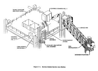
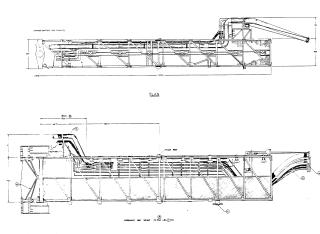
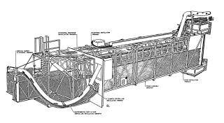
Arm No.8 : Service Module (inflight)

Provides air conditioning, exhaust, cooling, electrical, pneumatic interface. A pneumatic / mechanical lanyard system is used to pull in the umbilical connector. Furthermore, a mechanical system assists. It takes up to 9.0 seconds to disconnect the arm.
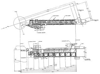
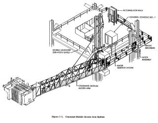
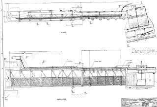
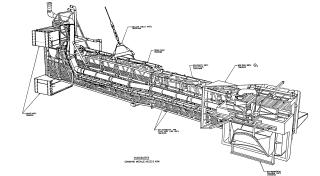
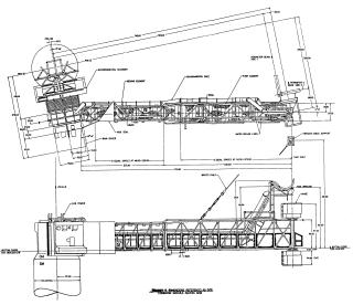
Arm No.9 : Command Module Access Arm (preflight)

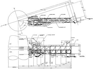
Provides astronaut access to spacecraft via the Environmental chamber so-called White Room. This arm can be folded and unfolded by a command from the LCC. It is separated to a park position (standby position) of 12 degrees : about 3 ft (1 m) from the spacecraft, from T-43 minutes until T-4 minutes. It takes 12 seconds to deploy from this position.
Saturn V Damping, Retract, and Reconnect System (DRRS)

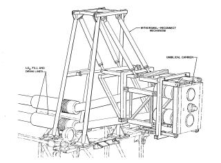
When the vehicle installed in the Pad is blown by the wind, karman vortices (vortex shedding) are generated below the wind. DRRS is a support prop for damping the vibration of Saturn V due to the vortex. This prop also has features for automatic deployment, connection and disconnection with vehicle, and retraction.
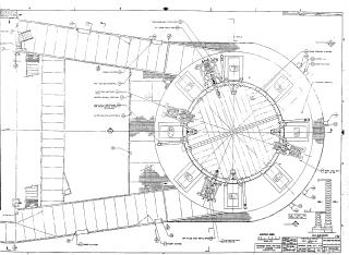
Launcher Base


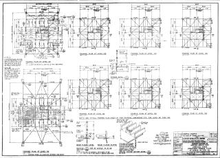
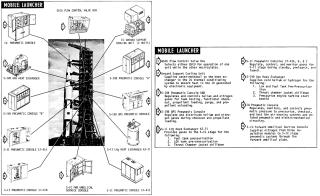
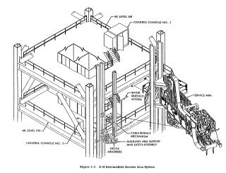
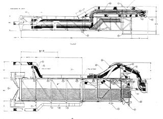
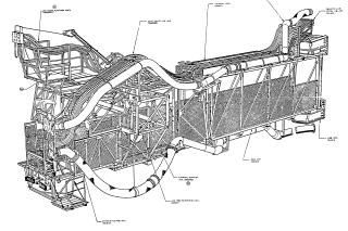
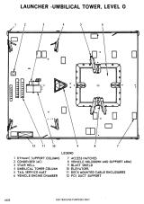
The grayed part that constitutes the lower part of ML is called Launcher Base. The length is 160ft 4inch (about 48.9m), width is 135ft (about 41.1m), height is 25ft (about 7.6m), and it is a two-story building consisting of floor A (upper floor) and B (lower floor). Made of lots of heavy duty steel girders, supporting the weight of LUT and vehicle.
Level 0
On the top of the Launcher Base, there are four Hold-Down Arms for securing the vehicle, and three Tail Service Masts (TSM) that connect to the lower end of the S-IC. Saturn V launch vehicle is installed here with the S-IC's Position II (Engine # 1, # 2) facing in the direction of the LUT.
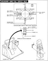
Hold-Down Arms

Four units are installed to surround the S-IC. This is used to secure the vehicle to ML during assembly and movement to the Pad.

Tail Service Masts(TSM)


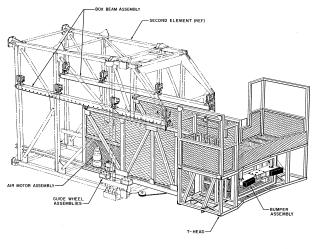
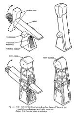
There are three Masts, No. 1-2, No. 3-2, and No. 3-4. The structure of the three masts is basically the same, but the number and type of cables to be connected are different. These three masts are mechanically separated and folded by the upward movement of the vehicle with the help of pushoff foot with pneumatic. It takes 3.0 seconds to disconnect the masts. If the pushoff foot fails, it is driven off by the counterweight mounted on the mast. In this case, the time taken for disconnection is 3.2 seconds.
TSM No.1-2
It is located north of position I, between Saturn V Position I and II, and connected to the Umbilical plate No. 2 of S-IC. Provides an interface for RP-1 fuel, 8 electricals, 10 pneumatics, hydraulic and cryogenic connections.

TSM No.3-2
It is located north of position III, between Saturn V Position II and III, and is connected to the Umbilical plate No. 3 of S-IC. Provides 2 air conditioning, 1 drainage duct, 10 pneumatics connection interface.
TSM No.3-4
It is located south of position III, between Saturn V Position III and IV, and is connected to the Umbilical plate No. 1 of S-IC. Provides LOX injection, exhaust line, 8 electricals, 11 pneumatics, hydraulic, cryogenic connection interface.
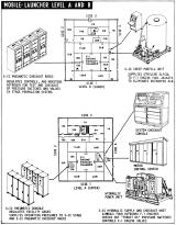
Floor A (Level A) : Upper floor

There are 21 rooms here. Digital acquisition unit, RCA 110A computer system, service arm operation control device, communication device, water deluge panels, and other control devices are installed here.
Floor B (Level B) : Lower floor

There are 22 rooms here. Hydraulic charging units, environmental control systems, electrical measuring devices, and terminal rooms for measurement and communication interfaces are installed here.
Exhaust Chamber
It is a square hole through the launcher base to pass the exhaust of engines. The size of one side is 45 ft (about 13.7 m). At the time of launch, the Flame Deflector is installed immediately below here. It is covered with a replaceable steel blast shield and is cooled by a water curtain which starts 2 seconds after liftoff.
Mount Mechanisms
This is six 22ft (about 6.7 m) high legs to support the ML. This height is sufficient for the crawler transporter to go under. These are used in Pad and VAB to fix ML in the correct position.
Extensible Columns
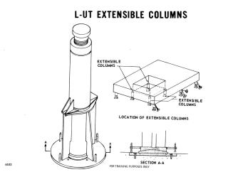
This is four removable hydraulic pedestals that support the ML. These are placed under the four corners of the Exhaust Chamber. In Pad, used to hold Satrun V which reaches 6 million pounds (3 thousand tons) or to suppress rebound at engine cutoff.
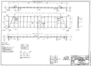
Drawings
Water Deluge System

The LUT and Launcher Base are equipped with the Water Deluge System, a system that sprays a large amount of water, for cooling and fire prevention at launch. As for the LUT, as soon as the service arms are retracted, watering starts to cool the arms. At Level 0 of the Launcher Base, there are 29 watering nozzles, and watering starts as the rocket lifts off. This watering starts at 50,000 gallons / minute for the first 30 seconds and continues at 20,000 gallons / minute thereafter. There is also a series of water spray nozzles on both walls of the Exhaust flame trench below the launch pad, which starts watering at 8,000 gallons / minute 10 seconds before liftoff. In addition, sprinkling nozzles are installed around the Pad, including the emergency escape routes of astronauts and engineers, to flush spilled fuel and reduce the occurrence of fire caused by fire powder.
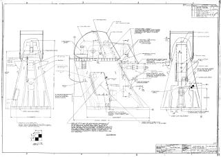
Milkstool


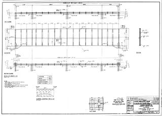
Drawings
Mobile Launcher History
ML-1

It was first used on May 25, 1966, the transfer of the SA-500F from the VAB to the LC-39A. The SA-500F was a full engineering mock-up designed to test the launch procedures and related equipment, although the fuel tank and equipment related to refueling and discharge, such as pumps and sensors, are installed, but engines were not attached and it could not fly. Also, this is partially different in appearance from the Saturn V that actually flew. This was later dismantled and used for various tests.
The first launch using the ML-1 is the Apollo 4 (SA-501), the first unmanned test flight of the Saturn V rocket. And it is ML-1 that launched APOLLO 11(SA-506) which succeeded in the first landing on the moon. Also, in the Skylab mission, it has been heavily remodeled and 'Milkstool' has been installed for use in launching Saturn IB booster . And it was this ML-1 that was used to launch the last Apollo spacecraft in the Apollo Soyuz Test Program (ASTP).
During the Space Shuttle era, it was modified to Mobile Launch Platform-3 (MLP-3) and used for the Space Shuttle launch to the Russian Space Station "Mir" in 1995, the first mission to the International Space Station in 1998, and the last Space Shuttle launch in 2011 e.t.c. Used for 33 launches. It remained in storage at VAB's High Bay 2 for some time, but is scheduled to be dismantled in the spring of 2023 to make room for the Artemis project's booster construction.
ML-2

This was used for the first time in Apollo 6 (SA-502), the second unmanned test flight of the Saturn V rocket launched on April 4, 1968. The design of the Tail Service Masts (TSM) was corrected as it suffered serious damage when the Apollo 4 was launched in ML-1 and applied to all subsequent Saturn V launches. ML-2 was later lowered the position of the access arm in the Skylab program. This allowed the access arm to be connected to the laboratory section(modified S-IV) of the Saturn V in Skylab 1.
During the Space Shuttle era, it was converted to the Mobile Launch Platform-2 (MLP-2) and used for over 40 launches, including the launch of the STS-51L Space Shuttle Challenger. It was then stored at mobile servicing structure park side for a while, but was dismantled in early 2021 to build a new ML-1 (different from the Apollo-era ML-1 above) for the Artemis program.
ML-3
It was first used with APOLLO 10(SA-505) , which was launched from Pad 39B on May 18, 1969. The Apollo 10 is the only rocket aimed at the moon launched from the Pad 39B.
During the Space Shuttle era, it was converted to Mobile Launch Platform-1 (MLP-1) and used for over 50 launches. After that, in the Artemis project, it was used to maintain the crawler way for the SLS launch.
After the end of the Apollo program
In the age of space shuttle, LUTs were removed from all three MLs. The Launcher Bases were then remodeled for the space shuttle to become Mobile Launcher Platforms (MLP).
The removed ML-2 and ML-3 LUTs were diverted to Pad-fixed launcher facility: Fixed Service Structure (FSS) for Space Shuttle launch. And new Rotating Service Structure (RSS) was attached to this. This functioned as a clean room that encased the Space Shuttle Cargo Bay.
ML-1's LUT and Milkstool were carefully dismantled in the mid-1980s to allow them to be rebuilt relatively easily later, as a result of the preservation campaign(Save The LUT) that took place at the time. They were detained outdoors behind the headquarters building of the John F. Kennedy Space Center (KSC). However, as a result of leaving it for 20 years, corrosion has progressed, and it has become possible for toxic lead paint to contaminate the soil. Because of this, it was scrapped in early 2004 and it is believed that it was used for part of the Three Gorges Dam project in the Hubei province of China.
Operation of Mobile Launcher
Mobile Launcher scale models


