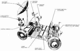
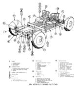
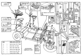
NASA Apollo project Lunar Roving Vehicle(LRV)
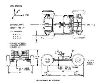
- length:122inches (310cm)
- width:6ft (183cm)
- wheel base:90inches (230cm)
- weight:on the Earth:462pounds(209kg) on the Moon:77pounds(35kg)
- ground clearance:14inches (35.5cm)
- turning radius:10ft (305cm)
- maximum speed:8.7mph (14km/h)
- power supply:36V primary silver-zinc batteries x 2, DC motor x 4
- range:about57miles (92km)
- manufacturer:BOEING Company Space Center Seattle, Washington. General Mortors Delco Electronics Division's Santa Barbara Operation California. (navigation system:BOEING Company Aerospace Group Electronics Organization)
Development
LRV was built by Boeing Company and their subsidiary : General Mortors Delco Electronics Division under a contract from NASA Marshall Space Flight Center. In 1969 when Apollo 11 succeeded to reach the Moon, Moon bike for one man ride was researched. Before release of LRV-1 for Apollo 15, following eight test vehicles were made for development.
- Full scale mock-up : for design verification.
- LM-LRV : for examine influence to LM structure while load on LM.
- two One sixth weight units : for develop Deployment System mechanism
- Mobility test unit : to prove the drive system.
- Nnormal Earth-gravity unit : for astronaut training o the Earth made by Delco Electronics.
- Vibration unit : to uncover any potential weakness in structual design.
- Qualification unit : tested under the conditions expected on the Moon surface.

LRV-1 was released to NASA at 14.Mar.1971. It was only 17 month after Boeing start to develop LRV. It is said that this was phenomenal speed, considering that all Apollo units (from CSM to spacesuits) took 50-60 months from start of development to shipment.

Performance
LRV will carry total about 1140 pounds (517kg), include two astronauts and their life support system(PLSS), scientific experimentation materials about 340 pounds, lunar samples, This is over twice its own weight, In comparison, the average family automobile can carry only about half its weight. And the operational lifetime of the LRV on the Moon was about 78 hours during the lunar day.
The LRV can climb over obstacle one-foot high from standing start, and cross 28-inch crevasses. The fully loaded vehicle will be able to climb and descend slopes as steep as 25 degrees. A parking brake will hold the LRV on slopesup to 35 degrees. The LRV can run on the slope of 45 degree in pitch and roll with full load.
It's maximum speed reach 14km/h in Apollo 15 mission, and 17km/h in Apollo 16.

Structure
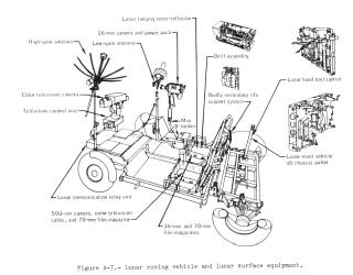
Floor panels of the chassis were beaded aluminum panels. Ground clearance was kept from 17inch(empty) to 14inch(full load) by dumper. Two seats are tubular aluminum frames spanned by nylon. They are folded flat onto the center chassis and unfolded somewhat like a lawn chair by the astronauts.

The wheels are an open wire mesh design with a chevron tread covering 50 percent of the surface contact area. Each wheel is driven by its own separate traction drive assembly consisting of a harmonic drive reduction unit, drive motor, and blake assembly. And fiberglass fender was attached at each wheel. the part of the fender is furnished by astronauts on the moon.
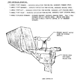
The drive motor were direct-current series, brush-type 36VDC, 1/4 horsepower motor. Each motor is instrumented for thermal monitoring. A thermal switch at each motor will close when its upper operating temperature is approached. The harmonic drive reduction unit reduces the motor speed at the rate of 80:1 and allows continuous application of power to the wheels at all speeds without requiring gear shifting. Brake was mechanical, and controlled from hand controller by wire.
The front and rear steering assemblies are mechanically independent of each other. Provision is made to steer with either set of wheels (or both sets). In the event of a steering malfunction, one set of wheels may be disconnected mechanically, and the misson can continue using the active steering system. Maximum travel of the steering linkage results in an outer wheel angle of 22 degrees and an inner wheel angle of 50 degrees.

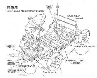
DGU:DIRECTIONAL GYRO UNIT and SPU:SIGNAL PROCESSING UNIT were installed on on front chassis too. DGU was used to know LRV heading direction and the north direction of the Moon. And SPU carries out digital and analog computer functions. These equipments are coverd with multilayered aluminized mylar and nylon netting insulation blanket with a white beta cloth. Aluminum thermal straps connected to the SPU and DGU transfer heat away from the electronic components and store it in the batteries and fusible mass heat sinks. At the end of the lunar sortie, astronauts open fiberglass dust covers to expose fused silica thermal mirrors mounted on top of the batteries. When the batteries reach their lower limit operating temperature of approximately 45 degrees Fahrenheit.
How to drive


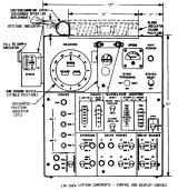
Control and Display Console
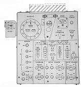
The Control and Display Console is divided into two main parts. navigaion on the upper section of the panel and controls for switching and monitoring of electrical loads on the lower section.

- INTEGRATED POSITION INDICATOR(IPI) / HEADING INDICATOR
- displays the LRV heading with respect to lunar north.
- BEARING INDICATOR
- shows bearing to the LM.
- DISTANCE INDICATOR
- reports distance traveled by the LRV in increments of 0.1 kilometer. This dispaly is driven from the navigation signal processing unit which, in turn, receives its inputs from the third-fastest traction drive odometer to compensate for wheel slipping.
- RANGE INDICATOR
- shows the distance to the LM.
- ATTITUDE INDICATOR
- provides indications of LRV pitch and roll. To read roll angles, the indicator is rotated forward, which exposes the ROLL scale to the left crewman. This indication is read by the crew and reported to the Mission Control Center.
- SUN SHADOW DEVICE
- determines the LRV heading with respect to the sun. This heading can be compared with the gyro heading at regular intervals as a check against gyro drift. When lifted into position, the device casts a shadow on a graduated scale.
- SPEED INDICATOR
- shows LRV velocity from 0 to 20 km/h. This display is driven by the odometer pulses from the right rear wheel.
- GYRO TORQUING SWITCH
- adjusts the navigation gyro to correct the HEADING indication. Moving the switch RIGHT moves the heading scale counterclockwise; with the switch in LEFT, the scale rotetes clockwise.
- NAV POWER CIRCUIT BREAKER
- used to route power from the main busses to the navigation subsystem.
- SYSTEM RESET SWITCH
- used to reset the BEARING/DISTANCE/RANGE digital displays to zero.
- POWER SECTION
- contains the circuit breakers that connect the batteries with the main power busses, the auxiliary outlet circuit breaker, and the circuit breakers and controlling switch for the +-15 VDC power to the pulse-width modulators. With four main power busses, any principal load, sch as a drive motor, steering motor, etc., may be connected to any battery.
- STEERING SECTION
- circuit breaker and switch for each of the two steering motors.
- DRIVE POWER SECTION
- circuit breaker and switch for each of the four drive motors.
- DRIVE ENABLE SECTION
- contains a switch for each drive motor which permits the driver to select either pulse-width modulator(PWM) 1 or 2.
- POWER/TEMPERATURE MONITOR
- provides a status of the vehicle's electrical system and the temperatures of the batteries and motors. Battery voltage and current flow are displayed on the same meter. The position of the "volts-amps" switch determines whitch of the two is being displayed.
- CAUTION AND WARNING SYSTEM
- gives the astronauts a visual warning that one of the batteries or traction drive motors is overheating. A spring-loaded, hinged "Alarm" panel, located on top of the console, is held down by a magnet.
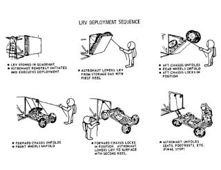
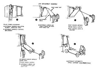
Deployment System


Post Deployment Activities

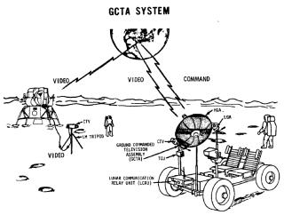
In driving, the high-gain antenna will be locked. So TV transmission is only possible when the vehicle has stopped. However, the low-gain antenna can be oriented while driving and voice communications are possible at all times.
At the conclusion of each EVA, the crew will park the LRV so it can be viewed from LM and power down all LRV systems. Battery dust covers will be raised to permit accumulated system heat rejection to the space environment.
LRV scale model
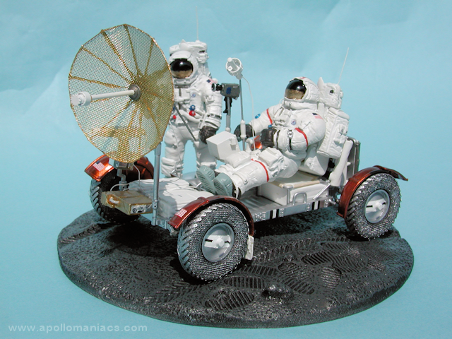
Photos of the LRV scale model posted on this site, is a 1/32 scale resin assembly kit made of EVA model. It is a realistic precision model with a total of 120 parts. Unfortunately, however, the shop was closed with the death of the owner. It is a kit that can not be obtained now.
Drawings
Related document download
Related books and videos
-
Lunar Rover Manual: 1971-1972 (Apollo 15-17; LRV1-3 & 1G Trainer)

Haynes Publishing UK December 1, 2012 USD32.95
Continuing the popular Haynes Owners' Workshop Manual space series, which currently comprises Apollo 11 Manual and NASA Space Shuttle Manual, this unique book provides an insight into the only car ever built to be driven on the surface of another world. With a Foreword by the first Apollo astronaut to drive it on the Moon, Dave Scott, and published to coincide with the 40th anniversary of mankind’s final drive on the Moon in December 2012.
-
Apollo Lunar Roving Vehicle Operations Handbook

Periscope Film LLC January 25, 2012 USD27.46
Developed in only 17 months at a cost of 38 million dollars, the Lunar Roving Vehicle (LRV) greatly expanded the survey range of the astronauts on Apollo 15, 16 and 17. Designed to operate in the low-gravity vacuum of the Moon, the LRV boasted an ingenious design that allowed it to be folded up and stored inside the Lunar Module. It would then be deployed using a system of pulleys and brake reels. The LRV's frame was made of aluminum alloy 2219 tubing assemblies, giving the vehicle a fairly small mass of 210kg but allowing it to carry up to 490kg on the lunar surface.
-
Lunar and Planetary Rovers: The Wheels of Apollo and the Quest for Mars

Springer-Verlag 2006/8/1 USD39.95
The Wheels of Apollo and the Quest for Mars fills a need for a complete history of the Lunar Roving Vehicle used on Apollo 15, 16 and 17, drawing on many photographs never before published. It will also tell the story of the successful robotic rovers used on Mars, and will conclude with a description of the new designs of rovers planned for The New Vision for Exploration now underway at NASA. In the Introduction, Anthony Young discusses the influence of art and images in both books and magazines that sparked interest in manned space travel. The Cold War launched the Space Race between the United States and the Soviet Union and the Mercury, Gemini and Apollo missions are provided in overview as a prelude to following chapters.


