

Computers for Apollo Program
In Apollo project, many computers were active in many places like spacecrafts, Saturn boosters, computer center on the ground. However, at that time it was the early days of computers, so NASA had to work with MIT (Massachusetts Institute of Technology), IBM (International Business Machines Corporation) and others to develop new technologies one after another.Navigation for Mercury spacecraft
Mercury spacecraft did not carry any kind of computer, and the flight course was entrusted to Atlas Booster's guidance system. Re-entry course was calculated at ground Real-Time Computing center (RTCC), and reverse injection time, injection attitude, etc. were transmitted to the spacecraft.Computer on Gemini spacecraft

In Gemini project, "Gemini digital computer" was installed, in order to complex trajectory change for mastering rendezvous technology required in Apollo project, backup of Titan II booster guidance system for safe launch, improve accuracy of re-entry, and automate huge number of checks before launch.
On April 19, 1962, IBM Federal Systems Division consigned development of the computer for $ 266 million, and by December 1965 had shipped 20 devices to NASA. The housing was 18.9 inches (48 cm) hight, 14.5 inches (37 cm) width, 12.75 inches (32 cm) depth, and weighed 58.98 pounds (About 26.75 kg). It was built with only IC-free electronic components (discrete: single-function semiconductors) and was mounted on unpressurized equipment bay, to the left of commander's seat of Gemini spacecraft. Since this computer has no redundancy at all, it had to rely on backup of the ground system in case of failure.
Hardware
This computer was a serial operation that processes one bit at a time, instruction cycle was 140 ms, numbers are represented in fixed point, arithmetic bit rate was 500 kilocycles, and memory cycle rate was half of that.
")
Ferrite core was used for main memory. It consists of 39 bits of one word, and has a 64 x 64 bit array of 39 planes, for a total of 4,096 words to be stored. One word was divided into three 13-bit "syllable", instruction was one syllable (13 bits) and data was two syllables (26 bits). Therefore, up to three instructions can be stored in one word, but instructions using data use one entire word at a time.
")
Also, magnetic tape system was mounted as an external storage device. At each phase of flight, necessary program was read from magnetic tape into core memory and then executed. Gemini spacecraft is the first to read programs from magnetic tape in space. The magnetic tape unit was about 700 cubic inches (About 0.01 cubic meter) and weighs 26 pounds (Approx. 11.8 kg) and was mounted on Gemini spacecraft adapter module. It has a storage capacity of 1,170,000 bits, and it takes six minutes to load a program from tape to core memory.
In order to improve reading accuracy, data was written in three places on the tape, and when reading into memory, these three data were stored in memory through a majority circuit. This method was also adopted by Space Shuttle. The first program read from tape in space was Gemini 8 mission, It was used to load re-entry program within the spacecraft that started spinning due to malfunction of the attitude control engine during docking with Agena target vehicle.
Software
The programming language was assembler. The compilation output from FORTRAN, just appeared at that time, was inefficient and did not fit into Gemini spacecraft computer resources. A total of nine versions of this program, called "Gemini Math Flow", have been developed. The final version of "Math Flow Seven" was used in Gemini 8 to 12 and was divided into six modules: Executor, Prelaunch, Ascent, Catch-Up, Rendezvous, and Re-Entry. Executor was used simultaneously with other modules as needed.
The program specifications were compiled by McDonnell-Douglas as a Specification Control Document (SCD) and sent to the IBM Space Guidance Center. There, FORTRAN program was developed to verify that the equations of guidance are correct.
User interfaces
Gemini spacecraft computer had three types of interfaces: Manual Data Insertion Unit (MDUI) and Incremental Velocity Indicator (IVI), in addition to control interface of the computer.
")
The control interface consisted of a mode switch, a start button, a malfunction light, a computation light, and a reset switch. The mode switch is a selector switch with seven selection positions for selecting one of the measurement program or the calculation program. Start button was used to execute selected program loaded into the computer's memory. When reset switch was pressed, the computer performs startup diagnostics and becomes operational.
")
The MDIU consisted of two parts: a 10 digit keyboard and a 7 digit register (display). The register is an odometer type rotary display, first two digits of which indicate a memory address and can display up to 99 logical addresses. And remaining 5 digits displayed data. When an error occurs, all digits are displayed as zero. When first digit of data is 9, it represents a negative number. In this case, second and subsequent digits indicate the value.
IVI displayed speed increment required or result of a powered maneuver. Three numerical values were displayed in units of feet-per-second for longitudinal axis, vertical axis, and horizontal axis.
During lift-off ascent, the computer acted as a backup for the booster. And on orbit, the computer could be shut down to save power until start of powered maneuver. Due to the nature of core memory, programs and data magnetically stored in the core will not volatilize even if power is turned off. For this reason, it was possible to load next module set from auxiliary tape memory as needed, enter necessary parameters, and shut down machine until just before use. After power was restored, it took 20 seconds to execute startup diagnosis. After diagnostics run successfully, loaded program was available and all parameters remained.
Gemini spacecraft computer was
- First digital computer mounted on manned spacecraft
- First use of nondestructive read-out core memory
- IBM's first complete silicon semiconductor computer
- First to use glass delay lines as resistors
- First airborne or spacecraft computer to use auxiliary storage
Apollo Guidance Computer (AGC)
Features required for onboard computers
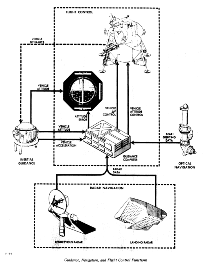
NASA, who initially wanted to avoid using computers as far as possible on the ground, changed its policy as the Apollo program took shape. Not only to find out position of spacecraft in flight, but also calculation of reverse injection for entering lunar orbit was processed by computer on the ground, and it was sent to spacecraft. Ultimately, autonomy of Apollo spacecraft (value of onboard computer) was reduced to one point of being able to safely return to the earth without help of ground. Nevertheless, the onboard computer not only performs navigation calculations, but also manages navigation and guidance components, as well as providing timing signals to 20 onboard systems, and many other tasks, so developers called it "the fourth crew member."
Beginning of development
On August 9, 1961, NASA officially selected MIT Instrumentation Lab as manufacturer and developer of Apollo's guidance and navigation systems. MIT had previously developed guidance systems and small computers, such as those used by Polaris missiles and Mars unmanned spacecrafts. The Polaris missile guidance development team at MIT has almost been transferred to the development team for Apollo program. However, at that time the specifications required for development had not been clarified, and MIT could not decide its development policy until the end of 1962. Also, even if the specification was clear from the beginning, it is said that it was impossible to achieve with technology of the early 1960s. Apollo spacecraft computer development was one of NASA's first huge real-time software developments.
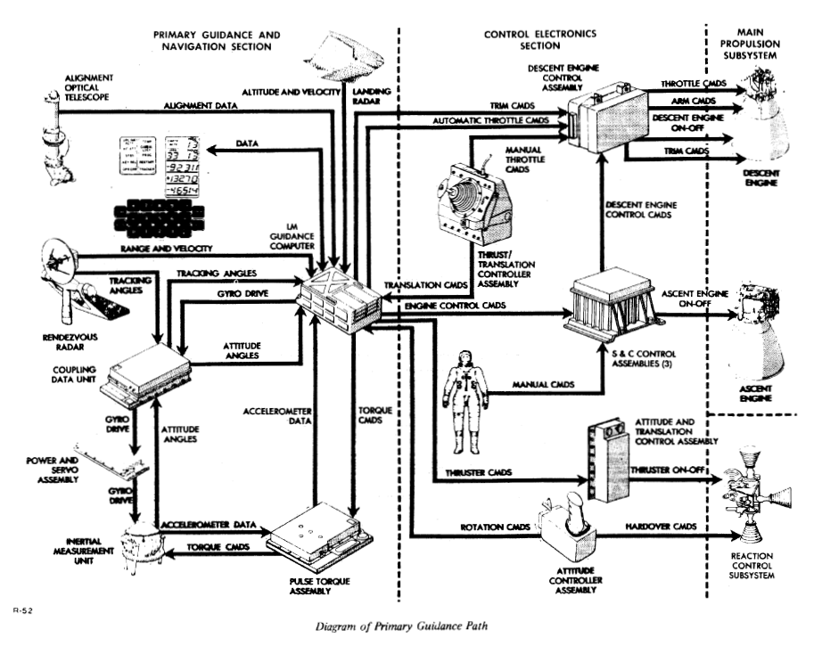
PGNCS "pings" and AGS


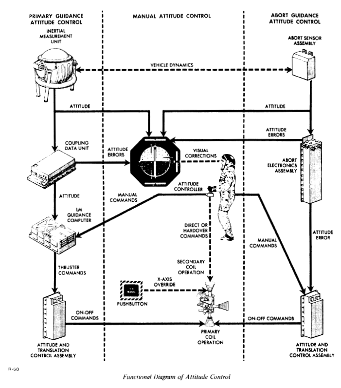
Command Module: CM and Lunar Module: LM were equipped with guidance system of same specification one by one. The one mounted on CM is responsible for navigation between the earth and the moon, the one mounted on LM was responsible for landing on the moon, taking off from there, and rendezvous with CM. This system was called Primary Guidance, Navigation, and Control System (PGNCS pronounced "pings"). For guidance of CM, ground computer performs backup, and when PGNCS breaks down, manual operation is performed using data from ground. Conversely, when communication with ground is lost, CM alone has ability to return to the earth. On the other hand, due to delay in communication from the moon, it is not possible to get help of ground computer when landing on the moon. So LM has been equipped with Abort Guidance System (AGS) as a backup system. This is to support the flight from abort landing and rendezvous with CM when LM PGNCS breaks down at the time of landing on the moon. AGS does not have the ability to perform lunar landings on behalf of PGNCS. Apollo spacecraft was to be equipped with a total of three computers: PGNCS for CM and LM, and AGS for LM.
Two hardware designs
.")
.")
Apollo's guidance computer, like the spacecraft, has two designs, Block I and Block II. Block I is built on same technology as guidance system for Polaris missiles, and Block II is a new one with an original architecture to cope with rendezvous flight and improve reliability.

IBM was developing Saturn V computer while MIT was developing Apollo spacecraft computer, and at NASA there has been a move to integrate these. It is an idea to divert Saturn V's computer to Apollo spacecraft. However, this was rejected due to cost of reprogramming, and difficulty to mount Saturn V computer on Apollo spacecraft bcause of it's size.

Following progress in development of Apollo spacecraft, Block I computer was used in unmanned and early manned flight, mainly in missions to fly the Earth's orbit, Block II was developed for use on more complex missions, including installation on LM.
In order to ensure reliability, it was considered to duplicate the computer, but was impossible in terms of power, weight and size. Block I computer was modularized and structurally it could be repaired in flight if spare parts were prepared. However, in practice, this was not realized because the emphasis was placed on improvement of reliability by tight sealing rather than ease of repair. In Block II, malfunction detection function has been improved and reliability has been further improved.

Although core transistors were used in the circuit of Block I, there was a problem that rewriting was necessary when data was read (destructive read), and the clock cycle was not stable. Therefore, MIT decided to adopt IC (integrated circuit) composed of direct-coupled transistor logic (DCTL) NOR gates. By replacing all circuits with this NOR gate, system was simplified and reliability was improved. This fixed it's machine cycle to 11.7 ms. Compared to core transistor, speed is doubled and cycle time is fixed. Also, compared to Block I, the memory capacity has doubled, has higher input / output performance, consumes less power, becomes smaller, and improves reliability. However, IC was still a young technology for three years at that time, and it took some time to gain the trust of NASA. After the decision to use NOR IC in the fall of 1962, 60% of IC production in the United States was used for Apollo computer prototype in the summer of 1963. This is one of the few cases where NASA's requirements had become a direct impetus for the computer industry.
AGC hardware structure

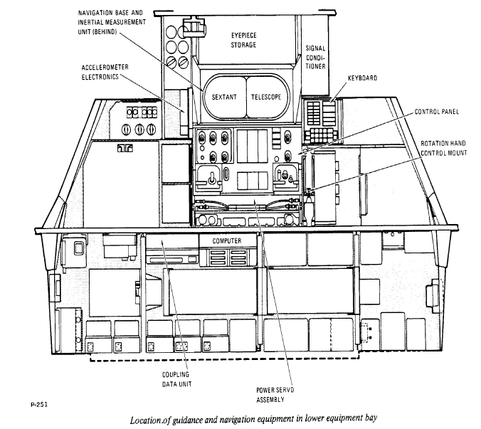
The Block II AGC measures 24 inches x 12.5 inches x 6 inches (Approx. 61 cm x 32 cm x 15 cm), weighs 70.1 lbs (Approx. 32 kg), and is powered 28 V DC and 70 W power. It was mounted on CM's lower equipment bay, and the same was mounted on LM. And operation was done with display and keyboard units (DSKY, pronounced "disky"). CM had two DSKYs, one at main control panel in front of commander's seat and the other at the back of CM, near optical instruments at navigator station. ACG itself was also stored here. In addition, DSKY of navigator station had a "MARK" button that sends a signal to computer when position of star has been determined. One DSKY was installed on control panel of LM. DSKY had a size of 8 inches x 8 inches x 7 inches (about 20 cm x 20 cm x 18 cm) and a weight of 17.5 pounds (about 8 kg).
 mounted in the Main Display Console of the Apollo 13 spacecraft, Odyssey.")
Word length of AGC was 16 bits, and single precision data consisted of 14 bits, a code bit (1 represents minus), and a parity bit (odd parity). Double precision data consisted of 2 words, and triple precision data consisted of 3 words. Data were recorded as fractions and all numbers were expressed as less than one. Three double precision data were used to record 3D vectors.
Instruction word used bits 15 to 13 (numbered from left to right in descending order) as an octal operation code. Address was expressed by 12 bits of bit 12 to bit 1.
Computer circuit was in two trays of 24 modules. In each module, two sets of boards mounted with 60 flat packs (so-called ICs) equipped with 72-pin connectors were incorporated. Tray A has logic circuit, interface, power supply, and tray B was equipped with memory, memory control circuit, analog alarm device, and clocks. The clock frequency was 1 MHz, and all the units of the computer were hermetically sealed.
Block II memory consisted of erasable core memorys and six modules of core rope fixed memorys.
AGC was equipped with one adder, 16 I / O channels, and following 7 registers.
| register | name | description |
|---|---|---|
| 00000 | A | The accumulator |
| 000001 | L | The lower accumulator |
| 000002 | Q | The return address register |
| 000003 | EB | The erasable bank register |
| 000004 | FB | The fixed bank register |
| 000005 | Z | The next address |
| 000006 | BB | The both bank register (data stored in EB and FB were automatically together here) |
Maximum value that can be expressed by a 12-bit address is 8,192 entries, but the memory capacity of AGC has exceeded this four times. So memory was divided and designated into "banks". Erasable memory (so-called RAM) banks was represented by 3 bits, and fixed memory (so-called ROM) banks was represented by 5 bits. Furthermore, for addresses requiring a total of 16 bits, "superbank bits" were used to indicate that address bits of instruction word and value of fixed bank data register (FB) should be concatenated. These complex addressing schemes have simplified hardware but increased software complexity.
Memory
In the original design of MIT, ROM had only 4k words and RAM had only 256 words. This became 10K words for ROM and 1K words for RAM around June 1963. Then ROM was expanded to 12K words and later to 24K words, the final result was 36K words for ROM and 2K words for RAM.
For erasable memory (RAM), coincident-current ferrite cores, similar to a Gemini computer, were used. For fixed memory (ROM), core ropes similar in material to erasable memory, but with a completely different design, were used.
Core Rope
")
Core of erasable memory records one bit of information per one in different directions of magnetization. On the other hand, core of the core rope can record four bits of information per one. Each core of the core rope acts as a small transformer and can connect up to 64 wires (4 sets of 16 bit words) to each core. If wire was passing through a specific core, "1" was read, and if wire was bypassing a specific core, "0" was read. For example, to store binary data "10010001000001111" in the core rope, the first, fourth, eighth, thirteenth through sixteenth wires are passed through the core and the rest are bypassed.
")
Core rope consisted of six modules, and each module recorded 16 bits x 6,144 words. Each module is further divided into six "banks" of 1,024 words each, it consisted of a total of 36 banks (6 modules x 6 banks). First two banks were called "fixed-fixed memory" and could be directly addressed with 12 bits in instruction word. Remaining 34 banks were specified using 5-bit contents of fixed bank register and 10 bits of instruction word.
Since core rope memory records a program by wiring, the time for its manufacture and test was required. Software to be stored had to be completed months before the mission implementation. And once completed, correction was not easy. Because of this, software needed to be perfect as well as complete quickly.
First AGC-equipped flight was AS-202 mission for unmanned test flight launched on August 25, 1966. It was loaded with Block I AGC and software named CORONA, which was completed in January.
Core Rope mechanism

This figure shows the principle of core rope. Vertically aligned rectangles in the middle indicates cores, and binary numbers above them indicates values stored in the core. For example, in the core at the left end, a value of "1000" is recorded. This is achieved by top wire passing through the core and other three wires bypassing the core. When this core is selected for reading data, "1" is read to the wire passing through the core. And "0" is read to the wire which does not pass through the core.
Software specification development
NASA and MIT formulated Guidance and Navigation System Operations Plan (GSOP) for each mission and clarified software requirements. NASA reviewed the GSOP 18 months, 16 months and 14 months prior to launch and "freezed" it at 13.5 months prior to launch. The program finished development in 10.5 months before launch and completed testing by 8 months ago. This software was stored at MIT, and magnetic tape recording it was sent to North American (CM manufacturer) and Grumman (LM manufacturer) and used for simulation. Four months before launch, core rope was completed and incorporated into the spacecraft. The program was developed using Honeywell 1800 computer and later IBM 36O.
Software structure
AGC has been a priority-interrupt system that can handle multiple jobs at one time. This is completely different from "round robin system" where time is evenly distributed to all jobs. The priority interrupt system is always running only one job with highest priority then. When the job is completed, job execution of equal or lower priority in the job queue is performed.
Apollo spacecraft management program included two programs related to job scheduling: "Executive" and "Waitlist". Executive managed up to seven "jobs" at a time, and Waitlist managed nine short "tasks". The execution time given to tasks in Waitlist was less than 4 milliseconds. If a task is run longer than that, it is promoted to "Job" status by the Waitlist and moved to Executive queue. Executive checks every 20 milliseconds for "jobs" and "tasks" that have higher priorities than those currently running. If there were no other jobs waiting, a program called "DUMMY JOB" was run until another job was queued. Executive also managed to display on DSKY.
Executive was also responsible for memory management. When one job was executed, twelve erasable memories were allocated, called "coreset". And additional 43 memory cells (VAC: vector accumulation) were allocated for vector operation when executing an interpreter language (described later) job. Finally, moon landing program used 8 core sets in LM and 7 core sets in CM, and additionally consumed 5 sets of VAC.
Software development
Assembler language was used for programming, but in addition to this, MIT has developed a higher-level, interpreter language dedicated to Apollo project, that translates into a series of subroutine calls at runtime. Assembler language had a total of 11 instructions, while interpreter language had 128 virtual instructions. Although this is slower than assembler, it can reduce memory usage. Also, large number of instructions in the interpreter means that it is easier to translate equation into a program than assembler. This improves coding speed and accuracy.
MIT staff gave computer programs a variety of imaginative names. Since Apollo was the name of the ancient god of the sun, 'SUN' was attached to many of its names, such as SUNDISK, SUNBURST, SUNDIAL. However, two main lunar flight programs were called "COLOSSUS" and "LUMINARY". Former beginning with "C" is the name of the program for CM, and latter beginning with "L" is the name of the program for LM.
NASA and MIT often call these program names and version numbers for short. For example, SOLRUM 55 is version 55 of SOLARIUM for AS 501 and 502 missions. Program COLOSSUS was used for the first time on Apollo 8 moon orbit.
Software restart
ACG had a function to "restart" when a failure occurs, such as voltage abnormality, clock abnormality, "rupt lock" state in which the system is stuck during an interrupt operation, or OS stall. When restart occurs, control is transferred to specified address. Program then looks at "phase table" to see which job to schedule first. Scheduled job is resumed from last set "restart point". Address of the restart point was stored in restart table. Programmers had to ensure that restart table entries and phase table entries were always kept at appropriate values at runtime in preparation for the occurrence of restarts. Restart also cleared all output channels, such as control jet commands, warning lights, and engine on / off commands, so it was assumed that dangerous situation would not occur due to the occurrence of a restart.
During Apollo 11 moon landing, software failure that caused restart occurred. This software was designed to prioritize incremental request of counter over instruction. That is, when certain hardware makes a request to increase count of values stored in memory, operating system interrupts current job, processes the request, and resumes suspended routine. It was predicted that if this incremental demand reached 85,000 times a second, it would stop all other jobs completely. Even if the number of requests is not so large, the operation of software may be delayed and restart may occur. At the time of Apollo 11 moon descent, rendezvous radar made a very large count increase request. And approximately 15% of computer system resources were consumed in this response. The situation caused restarts three times in 40 seconds when the LUMINARY program P64 was running during descent. As a result of this restart, a series of warnings were displayed on both spacecraft and mission control.


Operation of AGC
 of an Apollo spacecraft. (prepared by the Wichita State University Media Services)")
Two Block I DSKYs mounted on CM had different designs, while both Block II models had same design. Operating status of DSKY and computer could be monitored from ground. DSKY has 3 of two-digit displays such as PROG(ram), VERB and NOUN, three five-digit numeric (with signs) displays, 10 warning lights, and COMP ACTY (computer activity) light. There are also 19 keys (VERB, NOUN, CLEAR, KEY RELEASE, PROCEED, RESET, ENTER, PLUS, MINUS, numbers from 0 to 9).
Meaning of warning lights
| lights | meaning |
|---|---|
| COMP ACTY | Lights up when the computer is running a program. |
| UPLINK ACTY | Lights up when receiving data from the ground. |
| TEMP | Lights up when the temperature is out of tolerance. |
| NO ATT | Lights up when the inertial subsystem can not provide an attitude reference. |
| GIMBAL LOCK | Lights up when the middle gimbal angle exceeds 70 degrees. |
| STBY | Lights up when the computer system is in standby state. |
| PROG | Lights when the computer is waiting for the crew to enter additional information to complete the program. |
| KEY REL | Lights up when the computer needs control of DSKY to complete the program. The display of information may be overwritten by other routines or higher priority interrupts. The crew can press the KEY REL key to release the keyboard to the program requesting this. When the KEY REL light is on, the crew can talk to the requesting program through the DSKY by pressing that key. |
| RESTART | Lights up when the computer enters the restart program. It kept on during the Apollo 11 landing on the moon. |
| OPR ERR | Lights up when the computer detects a keyboard input error. |
| TRACKER | Lights when one of the optical coupling units (OCDU) or rendezvous radar fails. |
| lights | meaning |
|---|---|
| NO DAP | Warn that the digital autopilot has failed. |
| ALT, VEL | Warn that altitude and speed measurements exceed predetermined limits. |
- PROG
- Program number currently being executed by the computer (2 digits).
- VERB
- Verb number being input (2 digits).
- NOUN
- The noun number being input (2 digits).
- Three 5-digit numbers (including signs)
- Indicates various values in decimal or octal. When sign is displayed, it is a decimal number display, otherwise it is an octal number display.
Verb-Noun System
")
 and David R. Scott (left). James B. Irwin is mostly obscured to the right. (NASA photo SS-71-29952)")
Touching the key generates a software interrupt, allowing astronauts to launch programs from DSKY. ACG had about 40 programs and 30 subroutines. Use the Verb-Noun System to launch these programs and make other requests. Ordinary computers use the alphabet to enter commands, but ACG performs command input with a combination of VERB and NOUN numbers. Although 100 types of 00 to 99 can be specified for each, most of the meaning of each numerical value was determined for each mission. To start a new program, enter Verb 37.
For example, to start the rendezvous targeting program (P31), enter
[VERB][3][7][ENTER][3][1][ENTER]verb 50, noun 18 to specify flight angle.
Enter verb 06, noun 18 to monitor changes in numerical values during flight.
Enter verb 06, noun 84 to require speed change on next action.
Crew Procedures Division in Houston described the meaning of these numbers, which differ from mission to mission, in the CSM G & C checklist (so-called "cue cards", which are held in three rings).
The checklist included a list of stars used for navigation, a list of verbs, a list of nouns, a list of warning code, error handling and recovery, and a checklist of programs on the computer.
Note that for some functions, the "minkey" (minimum keystroke) option was available to allow astronauts to execute without the "approval" operation.
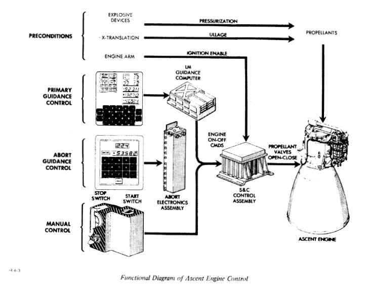
Abort Guidance System (AGS)

AGS operated independently of PGNCS and provided astronauts with position, speed, attitude and steering information. Even when LM flew behind the moon and could not communicate with ground control, it could independently verify navigation data. AGS was loaded and tested from Apollo 9 LM. The system was operated using various sensors fixed to LM rather than inertial guidance system. The entire system was only 3 cubic feet (about 0.08 cubic meters) and consisted of three major components:
- Abort Electronic Assembly (AEA)
- Computer body
- Abort Sensor Assembly (ASA)
- Inertial sensor
- Data Entry and Display Assembly (DEDA)
- Keyboard and display
Hardware of AGS

In the original design, AGS was not a computer. It was a sequencer with only 2,000 words of fixed memory, which did not have navigation functions. It's task was simply to launch LM into "clear" orbit (higher than any mountain on the moon). After that, LM will wait for rescue from CM. Then in the fall of 1964, the requirements were changed, and ability to rendezvous with CM more safely and automatically without external assistance was required. As a result, the manufacturer TRW decided to install a computer with 4,000 words of memory.
Computer developed for AGS was called MARCO 4418 (Man Rated Computer). This is an 18-bit machine with 1 sign bit and 17 data bits, and the instruction code was composed of a 5-bit op code and a 13-bit address unit. Numbers were stored in fixed-point, two's complement format, as in PGNCS. Twenty-seven instructions were available and execution time varied between 10 and 70 microseconds depending on the instruction being executed. The size of the computer was 5 inches x 8 inches x 23.75 inches (about 13 cm x 20 cm x 60 cm), the weight was 32.7 pounds (about 15 kg), and the power consumption was 90 watts. Memory is divided into a 2 kiloword fixed core (ROM) and a 2 kiloword erasable core (RAM), and access speed was inferior to PGNCS because of serial access. However, since the structures of fixed core and erasable core were the same, this capacity ratio could be changed.

DEDA was much smaller than DSKY and had limited functionality. The size was 5.5 inches x 6 inches x 5.19 inches (about 14 cm x 15 cm x 13 cm) and was mounted in front of pilot, on the right side of LM control panel, at waist level. There were 16 keys: CLEAR, READOUT, ENTER, HOLD, PLUS, MINUS, and 0-9, and one 9-digit display. The display was able to display a 3-digit address (octal number), a 1-digit sigh, and a 5-digit value. This was similar to Gemini spacecraft computer display.
Software of AGS
Two years before LM's first flight, as of 1966, size of the program used up almost 4k words of memory, and free memory remained only 20 words. In the early versions of the program, as with PGNCS, engine was stopped when it was restarted, and attitude was maintained. But it is very dangerous if this happens when LM is close to the moon surface, not when flying in space. For this reason, during restart, astronauts manually start engine if necessary.
NASA finally provided TRW with tentative orbit information and mission requirements 12.5 months before the mission, and 1.5 months ago, the magnetic tape containing the final program was released.
AGS was never actually used to abort mission, but was used on Apollo 11 mission in the final rendezvous and docking with CM to avoid problems encountered with rendezvous radar during landing on the moon. It was also used to monitor PGNCS in all missions.
Computer on Saturn booster
History of computer development

Of the 10 unmanned Saturn I rockets launched between 1961 and 1965, the first five did not use a computer for guidance. At the fifth launch, ASC-15 computer, developed by IBM for Titan rocket, was installed as a "passenger" and was used to test telemetry data transmission. And in the subsequent five missions, it was used for guidance. Also, when Saturn rocket developed into IB and V series, IU (Instrument Unit), including LVDC (Launch Vehicle Digital Computer), was mounted on S-IVB stage. In addition to the computer, LVDA (Launch Vehicle Data Adapter) works as an I / O front end, analog control circuits, and ST-124 guidance platform were installed here. In lunar landing mission, LVDC guided rocket from TLI (Trans Luner Insertion : Entry to the flight trajectory to the moon) to S-IVB stage separation.

LVDC, developed by IBM, was architecturally very similar to Gemini spacecraft's guidance computer. It had almost the same instruction set, and used 26-bit data word and 13-bit instructions. The difference with Gemini's computer is that memory is two-syllable locations (three for Gemini's spacecraft). IBM has also developed, for LVDC, first "Flatpack" integrated circuit series under the Advanced Saturn Technology Program, commissioned by Marshall Space Flight Center (MSFC). There were later used in IBM 360 series.
When computer was used directly for prelaunch checkout, MSFC purchased RCA 110 to communicate with IBM ASC-15 on Saturn I. After that, RCA extended memory core to 24 bits x 32K words, and added 32K words to magnetic drum. It was renamed RCA 110A and continued to be expanded to handle more communication lines. By the time Saturn V was completed, it became possible to record state of 1,512 signal lines.
History of gyro development

Inertial guidance system of Saturn rocket was controlled by gyro unit, gimbal system, and servo mechanism so as to always point in the same direction with respect to the space. Travel distance of the booster and deviation from scheduled flight course, which inertial guidance system detected, were stored in computer memory and used to control booster.
The A4 (V2) missile used two gyros named LEV-3. Later in Germany Kreissel Geralte GMB. H, a more accurate SG-66 gyro was developed and used in German missiles until the end of the war. Von Braun team moved to the United States developed an even better ST-80 with air bearings and mounted it on Redstone rocket in 1954. This developed in 1957 into the ST-90 mounted on Jupiter rocket. These were manufactured by Ford Instrument Company. Early Saturn I used ST-90 and IBM's ASC-15 computer, which was used with Titan II missile. And for Saturn V, ST-124 inertial guidance system has been developed that can withstand more complex and long-running missions.
Evolution of the IU

Development of IU began in parallel with development of Saturn I at the beginning of 1958 as an "in-house" project at Marshall Space Flight Center. IU mockup was completed in Huntsville on June 15, 1961, and it's flight was planned for Block II series of Saturn I rockets. Prior to this, in Saturn I Block I series, guidance and navigation units were housed in various cases (canisters) located at the top of the S-I stage (first stage), in the adapter (Forward Skirt Assembly). This included components such as telemetry, tracking, and ST-90 guidance platform and guidance signal processor. In addition, ST-124 inertial guidance system was installed as a "passenger" and was used for testing, for use in subsequent guidance Saturn I, Saturn IB, and Saturn V.

MSFC aimed to put ST-124 into practical use on SA-5 missions and later, and to link it with IBM computer. The rocket used in SA-5 mission was Saturn I's first Block II series. In the IU mounted on this mission, ST-90, ST-124, telemetry, a power supply, and a controller were mounted in a tubular case pressurized with inert gas for cooling.
On SA-9 flight, Saturn I was equipped with a new type of IU. This was similar to the IU applied later on Saturn IB and Saturn V flights. Equipments were no longer pressurized and mounted directly inside the cylindrical wall of IU. This reduced weight and halved the height of IU.
IBM was appointed as main contractor of IU in both Saturn IB and Saturn V versions in February 1964, and was responsible for manufacturing, testing, and shipping to the Kennedy Space Center. However, MSFC was to assume primary responsibility for the first four units for Saturn IB and their flights. In the first IU, 80% of hardware was classified as government-provided equipment. But at the fifth IU, this percentage dropped to 10%. Saturn IB and Saturn V IU were basically the same, as Saturn V was equipped with proven equipment with as few modifications as possible.
Unlike the other parts of the rocket developed elsewhere in the United States, IU was developed only in Huntsville, where MSFC is located.
Function and Configuration of IU
Basic functions of IU included guidance and control at all phases of flight, such as
- Rocket command and sequence processing, including engine cutoff and stage separation
- Launch rocket into Earth orbit
- Relay rocket position, function, and other data to the ground station
- Ability to put S-IVB, IU, CSM into orbit to the moon (TLI)
- S-IVB attitude control when taking out LM from S-IVB (transposition and docking)
- Operations to move S-IVB and IU away from CSM flight path on the moon route
There are three key devices for guidance and control:
- ST-124 stable platform
- LVDC : launch vehicle digital computer
- LVDA : launch vehicle data adapter


ST-124
ST-124 was a 3-DOF inertial platform manufactured by Bendix Corporation's Navigation and Control Division, spherical with a diameter of 53 cm and a weight of 52 kilograms, and most of the structural members and components are manufactured of beryllium. Final adjustment of this platform was not perform until the end of the launch countdown to maintain accuracy. This adjustment was performed by irradiating the small opening of IU with a beam from a precisely located theodolite close to launch pad. The beam passed through a small window of guiding platform where it was reflected by a pair of platform prisms and returned to the theodolite. The achievement of proper alignment can be known from acquisition light signal that reaches mission control center. As a result, ST-124 is switched from earth-fixed reference to space-fixed reference 5 seconds before lift-off.

ST-124 continued to supply speed and attitude data to guidance computer during flight, but no active guidance system was used during first stage burn. Both Saturn IB and Saturn V are affected by gusts, wind shears and jet stream when rising in the atmosphere. But if perform corrective action on such turbulent flow, applied stress can cause the rocket to break under the large gimbal motion from a powerful engine. Because of this, no corrections were made during the first stage burn, but the rocket flew according to only predetermined program stored in its guidance computer. If the rocket deviated from the predetermined path during first stage burn, ST-124 sensed this displacement and stored data in a computer for later correction. Then, during second and third stages burn, these stored data was sent through computer to guidance control system, returning rocket to course.
LVDC and LVDA
.")
.")
LVDC collected information and issued commands such as rocket checkout on orbit. LVDA is connected to almost all units of the flight system and functions as an input / output unit to LVDC for buffering digital data and performing DA / AD conversion. Comparing Saturn V and Saturn I LVDC and LVDA, Saturn V is 3 times faster, 4 times more memory capacity, 100W less power consumption, and 60 times more reliable. Furthermore, memory capacity of Saturn V could be doubled by addition of memory modules.
| Item | Saturn I | Saturn V |
|---|---|---|
| No. components | 12 000 | 80 000 |
| Weight (kg) | 95 | 114 |
| Volume (m3) | 1.1 | 1.6 |
| Total power (watts) | 540 | 438 |
| Operations (sec) | 3 200 | 9 600 |
| Storage capacity (bits) | 100 000 | 460 000 |
| Reliability (hrs) | 750 | 45 000 |
Four new design concepts have been incorporated into the computer to meet strict reliability and operating requirements, and to meet size and weight limitations. There were Duplex memory system, Unit logic devices, triple modular redundancy, and liquid-cooled magnesium-lithium chassis.
Duplex memory system
When intermittent failures occur, one memory system operates to correct the other memory system, reducing the possibility of system failure. The system consisted of six modules, operating as a pair of duplexed memories, each with a capacity of 4,096 words (1 word is 28 bits). If there were further special mission requirements, it was possible to mount two additional modules.
Unit logic devices

It features ultra-compact circuits, and with a system that is seven times more components than previous computers, is smaller, lighter, and runs three times faster. Each logic device was fabricated as a 7.6 mm square and 0.71 mm thick "wafer". There were a total of 8,918 such wafers, attached to dozens of "pages" of about 7.6 centimeters square in a computer.
Triple modular redundancy
All important circuits of both LVDC and LVDA have been tripled : triple modular redundancy. Designers had selected seven functional sections that can be experience catastrophic failure but may not be acceptable for reliability reasons. Each selected section was placed in three identical logic channels with the same configuration. The task for computer was presented simultaneously to each module, and the results of each were calculated independently and sent to majority voting circuit. And "vote" different from the other was discarded as an error, and it was possible to pass the voting circuit only when the same answer was obtained from two (or more) modules. This voting circuit did not significantly affect performance of the system. In the worst case, delay due to the voting process was about 100 nanoseconds. In addition, this computer unit occupying 0.6 cubic meters and weighing 35 kilograms could be subtracted and added (at 82 microseconds) while simultaneously dividing and multiplying (at 328 microseconds).
Magnesium-lithium chassis
This is the first time that a magnesium-lithium alloy has been used as a structural material for electronic circuits. This alloy is 25% lighter than magnesium and 50% lighter than aluminum. It has a very high weight-to-strength ratio, excellent thermal properties suitable for operation in space, and minimal mechanical vibration transfer properties. Beryllium was lighter than this, but was avoided due to the technical difficulties in machining and drilling and its toxicity.
In addition to IU, Saturn rocket was equipped with several tracking and control systems. Azusa system worked with ground station to measure rocket tilt and direction. C-band radar transponders assisted radar ground stations in measuring azimuth, elevation and distance. Commands and communications systems were used to update the computer, perform tests, add or delete specific messages, and recall specific parts of the computer memory bank. During the launch and orbit phases, sensors mounted on the entire rocket: transducers collected information on vibration, pressure, temperature, and various operations. A measurement and telemetry system then sent these data to ground station.
The power to operate this complex electronics consists of four 28 volt DC batteries configured with special distributors and regulators for both low voltage components such as computers and high currents for ST-124 inertial platform. The electrical system also included an emergency detection network to analyze rocket failures. Depending on severity of problem, it could decided to either launch automatic abort sequence or leave the decision to astronauts and NASA flight controllers.
Guidance and navigation of Saturn V

With Saturn V launch, the rocket actually “thinks for itself” when IU starts operating 5 seconds before liftoff. The control system initially performed a series of attitude control operations programmed according to the elapsed time. Twelve seconds after takeoff, IU's computer rolls the huge rocket into the proper flight direction, according to pre-programmed roll and pitch commands. At the same time, it controlled engine's gimbal to pitch the first stage to a defined angle of attack for acceleration. When IU received a signal that S-IC fuel tank propellant level had reached the designated point, it initiated a command to cut off engine of the first stage and then separated it. After ignition of second stage (S-II), the rocket is controlled by a concept called "path adaptive guidance" which leads the propellant to a trajectory that efficiently uses it. About once every two seconds, the computer checked rocket's current position and flight status, and compared it with optimal situation (altitude, velocity, residual propellant, etc.) desired at the end of the powered flight. And, if necessary, IU generated correction signals from computer to analog flight control computer via LVDA, and the analog flight control computer issued appropriate gimbal commands to engines. S-II engine cut-off and stage separation from S-IVB were performed when IU sensed a predetermined propellant level. By this time the rocket had reached about orbital altitude, so S-IVB ignition and burn was sufficient for a short time to ensure safe parking orbit altitude and speed.
Each stage of Saturn rocket was equipped with a propellant dispersion system (PDS) in case the mission needed to be discontinued. This is rocket destruction mechanism for terminating flight after astronauts escape from the rocket at any stage of the flight. The PDS system complies with regulations established by authorities of Air Force Eastern Test Range and was under the control of a range safety officer. For this reason, it is also called Range Safety System. Wireless device receives PDS command, decodes it, and chain of explosives destroys stage by bursting the propellant tank. The PDS system included an initiator assembly and a soft, linear explosives to tear the tank after engine shutdown. The explosives were strategically placed so that propellant could be sprayed to minimize explosion due to mixing of propellant when the tank was torn.
.")
IU included a program that controls both stage separation and retro (reverse thrust) rockets fire. The timing of stage separation sequence was set to the rated thrust of each stage so as to be implemented before losing the thrust and starting to fall. Separation of the stage is performed by cutting tension strap by explosive device around the stage. And retro rocket quickly pushed back separated stage, and next stage continues its flight with inertia for a while. Once proper distance was taken from separated stage, ullage control was performed to stabilize propellant prior to engine ignition. To slow down used stage and stabilize propellant in subsequent stages, MSFC designers used various rocket systems, including small solid propulsion motors and small liquid propulsion engines. Saturn rocket was equipped with more number of solid propellant system than liquid propellant rocket engine. Saturn I was equipped with a total of 32 different types of solid propellant motors. This was 31 for Saturn IB and 22 for Saturn V.
In S-IVB Earth Orbit Sequence, IU obtained latest data from ground station and calculated re-ignition time continuously.
IU managed S-IVB's roll, pitch and yaw using one main engine with direct thrust control, and liquid propellant auxiliary propulsion system (APS).
And after final check, IU controlled vehicle's entry into translunar trajectory (flight trajectory to the moon).
When IU reports that acceptable injection conditions are in place:
a set of dumpable solid retro rockets and APS perform ullage control,
subsequently, J-2 main stage injection and engine cutoff were performed.
Finally, when CSM and LM leave S-IVB and IU,
IU used third stage APS unit to stabilize its attitude for transposition and docking operations.
And about 6.5 hours after lift-off, IU's mission was over.
[ ullage control ]
Ullage is a jargon of old beer brewers, and refers to the gas-filled space above the liquid in the tank.
In rockets, ullage motor is injected before the start of the engine, and in reaction, fuel is collected at the bottom of the tank and fed into the engine.
Real-Time Computing Center (RTCC)
Beginning of the computing center
In June 1957, NASA established Real-Time Computing Center (RTCC), consisting of IBM 704 computers, on Pennsylvania Avenue in Washington, DC, under Vanguard program. This is the originator of NASA's flight control data center.
NASA signed an agreement with Western Electric on July 30, 1959 to develop Mercury project tracking and ground system. And by the end of 1959, IBM had a computer and software subcontract. In November 1960, data center previously located in Washington was moved to newly created Goddard Space Flight Center (GSFC). And in Mercury project, IBM 7090 mainframe installed here was used.
RTCC has been equipped with two IBM 7090 systems, called Mission Operational Computer and Dynamic Standby Computer, to ensure its reliability to withstand manned space missions. This was NASA's first redundant computer system, and Dynamic Standby Computer was performing same processing as Mission Operational Computer as a backup machine. Names of these two computers were used as they were until Apollo program. Switching from main computer to dynamic standby machine was a manual switching by human judgment. When John Glenn was flying in orbit on Earth with Mercury spacecraft, main computer failed for three minutes, and for the first time a standby was active.
")
The software used in Mercury project was called Mercury Monitor. This is an event-driven software written in assembler language, and its main functions are determination of capsule position, calculation of reignition time, warning to ground station of acquisition time, and landing place after reignition prediction. These were divided into three program groups, loaded from tape and executed when needed. And a program called "Monitor" was in charge of overall control. The development of this type of software was the first for IBM at that time. This became the basis of future multitasking operating systems.
In 1962 NASA accelerated its preparation for Gemini and Apollo projects. NASA has decided to bring both computers for manned space flight control and flight controllers to a complex center in Houston. From Gemini 1 to 3, GSFC's system ran as main, and Houston's system was used as an active backup. And from Gemini 4 (Gemini Project 2nd Manned Flight), Houston system became the main, and until the end of Gemini Project, GSFC system was used as a backup.
RTCC in Gemini and Apollo Project
In April, Ford's subsidiary Philco Corporation Western Development Laboratories began investigating requirements of new Mission Control Center. Initially, Philco was considering the following three proposals. Configuration using five IBM 7094 (successor to 7090, with improved OS:IBSYS and faster speeds), Or configuration using 9 units of UNIVAC 1107, IBM 7090, Philco 211, Or configuration that uses four Philco 212 or CDC 3600. Whatever configuration was chosen, it was clear that complexity of Gemini / Apollo data center will be much higher than two Mercury-era computers.
For subsequent NASA proposal request, IBM has proposed a configuration of three IBM 7094. Divide software into a mission computer program and a simulation computer program, one machine mainly runs a mission program, the other works as a dynamic backup, and third one is running simulation software to test the other two. This met the requirements of redundancy and preflight training and testing. However, reliability of these three machines was 0.9712, and slightly more than four machines were needed to achieve NASA specification of 0.9995. (This is one of the reasons that Philco proposed five.) At the time, IBM claimed that the reliability figures were misleading, and that during so-called "mission critical" phase, the reliability of three machines exceeded 0.9995.
First one of IBM 7094 arrived in 1963 and then it was set up at a temporary facility on Gulf Expressway with two others. They initially had 32K words of memory and 98K words of external core storage, and two IBM 1401s were used as input and output front ends. Ultimately, 608 IBM people worked on the project simultaneously, 400 of them working on software development.
These first three moved from temporary center to building 30 in Houston's manned spacecraft center. Two more computers were added later, eventually resulting in Philco's forecast. Additional two were used as ground system simulation computers and standby for future software development. Size and rating of machine has also been expanded to 7094-II model with 65,000 words of main core storage and 524,000 words of additional cores as high-speed auxiliary storage. Ground system simulator simulated tracking networks and other ground based mission management devices and was used to test software.
On Gemini 2 unmanned flight December 9, 1964, 26 months after IBM's contract with NASA, the software is ready to run as a backup, and then at Gemini 4, Mission Control was moved from Cape to Houston.
Gemini project software development
The key to flight system completion was mission computer program. Its function was concentrated on a control program called Executive, which took over function of Mercury Monitor. Under Executive, three major subprograms were working in sequence. NETCHECK performed automated testing of equipment and data flow throughout manned space flight network and performed pre-launch checks of spacecraft. This was a continuation of program CADFISS (Integrated Calculation and Data Flow Subsystem) used in Mercury project. ANALYZER performed post flight data organization. And Mission Operations Program System was at the center of the software responsible for all mission operations, such as trajectory calculation, telemetry, spacecraft environment, onboard computer backup, rendezvous calculation, and so on. It was divided into several modules, such as launch of the Agena target satellite (Agena launch), launch of Gemini spacecraft (Gemini launch), orbit, trajectory determination, mission planning, telemetry, digital commands, and re-entry. Furthermore, there were multiple subprograms in each section. Each subprogram was very sophisticated and powerful.
Software development system is called Compiler Operating System, which included a combination of FORTRAN / Mercury compilers called GAC (Gemini-Apollo Compiler), which made it possible to program in FORTRAN. Mercury compiler included all the functionality of IBSYS, IBM standard system of late 1950s, and SOS (Share Operating System), the predecessor of IBSYS.
Executive was a further refinement of real-time control program originally developed in Mercury project. The relatively generous size of 13,000 words, Executive, provided a priority-based multiprogramming environment.
IBM recognized that at the time the company made proposal, regular 32K memory on a 7094 machine was not enough. Commercial approach of storing waiting programs on tape did not meet size and speed requirements of software in Gemini project. That's why IBM added a Large Core Storage (LCS) bank to original machine. These memory banks were not directly addressable but acted as faster secondary memories. Programs stored on tape were loaded into LCS and transferred to primary storage as needed.
NASA thought that new high-level machines, in particular 360/75 could be used instead of 7094 for Apollo program. However, because size of software is very large, it was thought that LCS should be used continuously. While shipments of IBM's 360 series were delayed, CDC (Control Data Corporation) introduced faster, higher-performance 6600 series in 1965. Robert Seamans at NASA headquarters suggested that purchase CDC 6600 and let IBM maintain its software. CDC sues IBM to unfairly contract unfinished 360 to maintain the market, IBM has settled the court with a major concession of about $ 100 million. And IBM rushed to ship first 360 to Houston in time to block other vendors' moves. NASA announced the replacement of computer with 360 in its August 3, 1966 news release.
Renovation for the Apollo Project
While first three Apollo unmanned missions continued to support four remaining 7094 computers, IBM used 360 to develop software for Apollo moon flights. The system consisted of five 360s and LCSs. The OS of new machine was OS / 360, and program used until then could not be run as it is. Also, provision of priority interrupts in this standard operating system was not sufficient to perform the kind of processing required by Apollo program. From 1965, IBM has changed the operating system to real-time version of RTOS / 360. Thanks to modular software structure, subprograms written in FORTRAN could be moved to 360 relatively easily by compiling separately. However, assembler-based code had to be rewrite. Although the architecture was essentially unchanged, this work took as much time as it took to start up the original system.
Each 360 had one million bytes of main memory, about four times the size of 7094. In addition, 4 million bytes of LCS were added to each machine. However, the memory usage also increased according to the added space. With lack of memory, programmers have begun to develop unique "tricky" code to save a few words. This is a dangerous sign that further complicates program and reduces maintainability. Therefore, using the performance of 360, they decided to develop an important part of the software with FORTRAN instead of assembler.
When Apollo system went into operation, the frequency of use of dynamic standby computer decreased. In the first manned flight, Apollo 7 mission, only one computer was used for 181 hours, within 284 hours of support period including countdown and post-flight operations. Apollo 10 mission, which operated two spacecraft CSM and LM near the moon, was planning to use a standby computer five hours before each flight operation. Again, during the eight-day flight, support by two computers was planned only six times. In preparation for startup of offline standby computer when main computer fails, operator saved data at that time as a checkpoint tape every 1.5 hours. And, on May 20, 1969 during Apollo 10 mission, between Zulu (= UTC) 12:58 to 13:01, a failure occurred in Mission Operations Computer. At this time, standby was started using checkpoint tape created at 12:00, and no serious problem occurred.
Toward the age of Space Shuttle
IBM beat Computer Sciences Corporation, they again won a development contract for NASA ground support systems from the beginning of June 1974 to the 1980s. Five System 370/168 mainframe computers made up Shuttle Data Processing Complex, the successor to RTCC. Each has 8 million bytes of primary storage, constitutes virtual storage, and LCS type auxiliary storage is no longer needed. Instead, a magnetic disk was used. Three computers were used during mission operation. One is a mission machine, one is a dynamic standby computer, and the other is a payload operation control computer. It was replaced by IBM 3083 as a fourth generation mission control system at the end of the 1980s.
Related site
Apollo Guidance Computer (AGC)
Computer on Saturn booster
Real-Time Computing Center (RTCC)
Related books and videos
-
Hidden Figures: The American Dream and the Untold Story of the Black Women Mathematicians Who Helped Win the Space Race

William Morrow Paperbacks 2016/12/06 USD12.31
The phenomenal true story of the black female mathematicians at NASA whose calculations helped fuel some of America’s greatest achievements in space. Soon to be a major motion picture starring Taraji P. Henson, Octavia Spencer, Janelle Monae, Kirsten Dunst, and Kevin Costner.
 (US)
(UK)
(US)
(UK)
-
Digital Apollo: Human and Machine in Spaceflight (MIT Press)
The MIT Press 2011/09/30 USD22.78
As Apollo 11's Lunar Module descended toward the moon under automatic control, a program alarm in the guidance computer's software nearly caused a mission abort. Neil Armstrong responded by switching off the automatic mode and taking direct control. He stopped monitoring the computer and began flying the spacecraft, relying on skill to land it and earning praise for a triumph of human over machine. In Digital Apollo, engineer-historian David Mindell takes this famous moment as a starting point for an exploration of the relationship between humans and computers in the Apollo program.
(US)
(UK)
-
The Apollo Guidance Computer: Architecture and Operation
Praxis 2010/07/12 USD42.70
Designing a mission for a flight to the Moon requires balancing the demands of a wide array of spacecraft systems, with the details of tending each component generating complex and often contradictory requirements. More than any other system in the Apollo spacecraft, the Apollo Guidance Computer drove the capabilities of the lunar missions. In the 1960's, most computers filled an entire room yet the spacecraft's computer was required to be compact and require little power.
(US)
(UK)
-
Saturn V Apollo Lunar Orbital Rendezvous Planning Guide
Apogee Prime 2011/07/15 USD24.95
The Saturn V Apollo Lunar Orbital Rendezvous Planning Guide is a reprint of a rare document from the early 1960s in which the whole Apollo moon landing mission was presented and illustrated. The book includes a large fold-out of the Apollo mission as well as a fold-out of the Saturn V moon rocket. It includes illustrations of early iterations of the Lunar Module, maps of the Cape Canaveral launch sites, launch schedules for all of the Apollo test flights, detailed specifications and schematics of the Saturn V launch vehicle stages, construction schedules, engine summaries, information on the VAB, mobile crawlers, Umbilical towers, a DVD and more
(US)
(UK)
-
Mission Control
Gravitas Ventures 2017/07/27 USD24.99
At the heart of the Apollo space program and a remarkable decade of achievement was the team who worked in Mission Control.They were born against a backdrop of economic turmoil and global conflict. Some came from a rural lifestyle little changed from the 19th century. Others grew up in a gritty, blue-collar America of mines and smoke stacks. They ranged from kids straight out of college to those toughened by military service. But from such ordinary beginnings, an extraordinary team was born. They were setting out on what JFK called: “The most hazardous, dangerous, and greatest adventure upon which mankind has ever embarked” and through their testimony ? and the supporting voices of Apollo astronauts and modern NASA flight directors ? the film takes us from the faltering start of the program through the Mercury and Gemini missions, the tragedy of the Apollo 1 fire to the glories of the Moon landings.
(US)
(UK)
-
Hidden Figures
20th Century Fox 2017/04/11 USD19.99
The phenomenal true story of the black female mathematicians at NASA whose calculations helped fuel some of America’s greatest achievements in space. Soon to be a major motion picture starring Taraji P. Henson, Octavia Spencer, Janelle Monae, Kirsten Dunst, and Kevin Costner.
(US)
(UK)